CYV15G0404DXB
Once initialized, TXCLKx is allowed to drift in phase as much as ±180 degrees. If the input phase of TXCLKx drifts beyond the handling capacity of the phase align buffer, TXERRx is asserted to indicate the loss of data, and remains asserted until the phase align buffer is initialized. The phase of the TXCLKx relative to its associated internal character rate clock is initialized when the configuration latch PABRSTx is written as 0. When the associated TXERRx is deasserted, the phase align buffer is initialized and input characters are correctly captured.
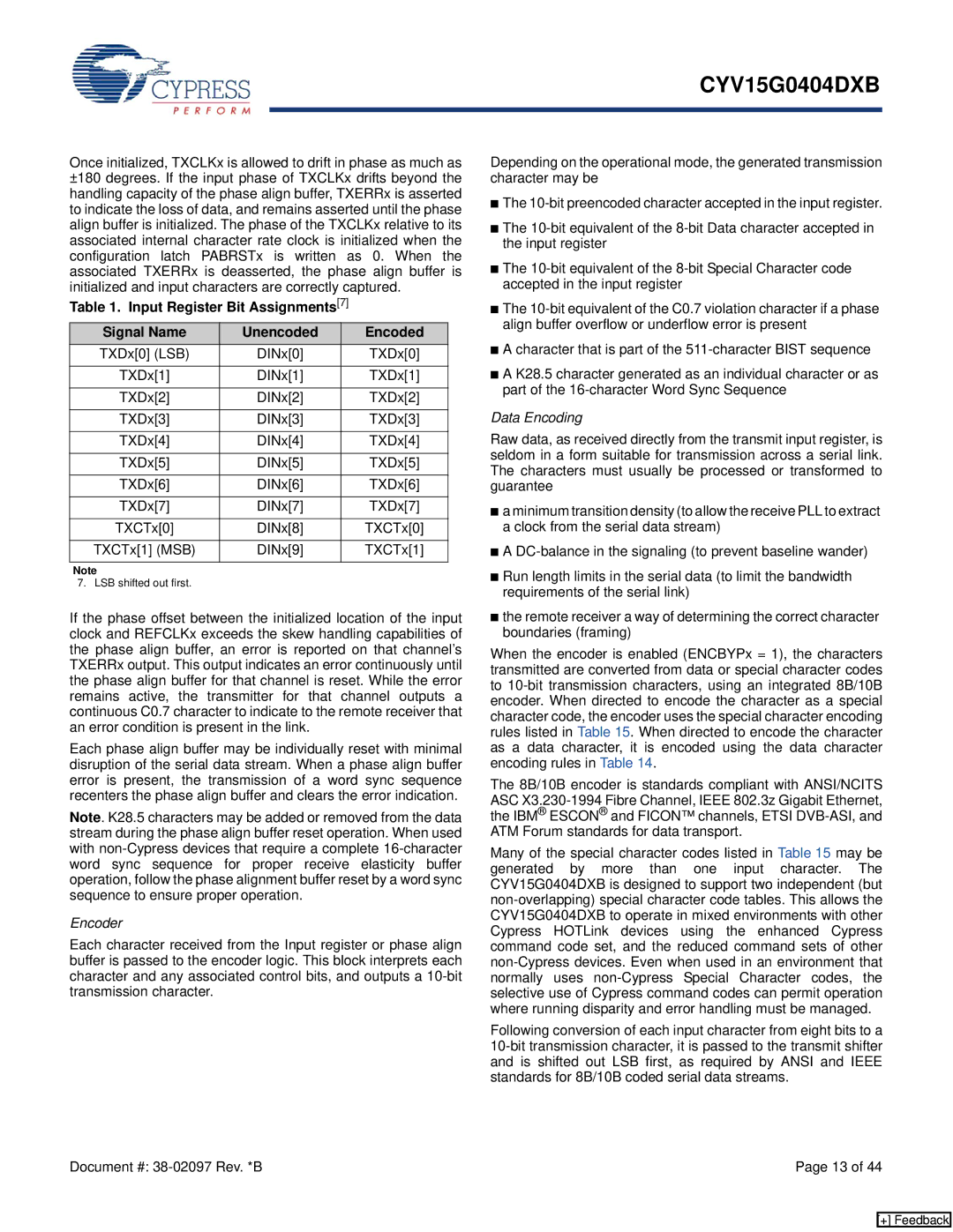
Table 1. Input Register Bit Assignments[7]
Signal Name | Unencoded | Encoded |
TXDx[0] (LSB) | DINx[0] | TXDx[0] |
|
|
|
TXDx[1] | DINx[1] | TXDx[1] |
|
|
|
TXDx[2] | DINx[2] | TXDx[2] |
|
|
|
TXDx[3] | DINx[3] | TXDx[3] |
|
|
|
TXDx[4] | DINx[4] | TXDx[4] |
|
|
|
TXDx[5] | DINx[5] | TXDx[5] |
|
|
|
TXDx[6] | DINx[6] | TXDx[6] |
|
|
|
TXDx[7] | DINx[7] | TXDx[7] |
|
|
|
TXCTx[0] | DINx[8] | TXCTx[0] |
|
|
|
TXCTx[1] (MSB) | DINx[9] | TXCTx[1] |
|
|
|
Note
7. LSB shifted out first.
If the phase offset between the initialized location of the input clock and REFCLKx exceeds the skew handling capabilities of the phase align buffer, an error is reported on that channel’s TXERRx output. This output indicates an error continuously until the phase align buffer for that channel is reset. While the error remains active, the transmitter for that channel outputs a continuous C0.7 character to indicate to the remote receiver that an error condition is present in the link.
Each phase align buffer may be individually reset with minimal disruption of the serial data stream. When a phase align buffer error is present, the transmission of a word sync sequence recenters the phase align buffer and clears the error indication.
Note. K28.5 characters may be added or removed from the data stream during the phase align buffer reset operation. When used with
Encoder
Each character received from the Input register or phase align buffer is passed to the encoder logic. This block interprets each character and any associated control bits, and outputs a
Depending on the operational mode, the generated transmission character may be
■The
■The
■The
■The
■A character that is part of the
■A K28.5 character generated as an individual character or as part of the
Data Encoding
Raw data, as received directly from the transmit input register, is seldom in a form suitable for transmission across a serial link. The characters must usually be processed or transformed to guarantee
■a minimum transition density (to allow the receive PLL to extract a clock from the serial data stream)
■A
■Run length limits in the serial data (to limit the bandwidth requirements of the serial link)
■the remote receiver a way of determining the correct character boundaries (framing)
When the encoder is enabled (ENCBYPx = 1), the characters transmitted are converted from data or special character codes to
The 8B/10B encoder is standards compliant with ANSI/NCITS ASC
Many of the special character codes listed in Table 15 may be generated by more than one input character. The CYV15G0404DXB is designed to support two independent (but
Following conversion of each input character from eight bits to a
Document #: | Page 13 of 44 |
[+] Feedback