|
|
| CYV15G0404DXB | ||
|
|
|
|
|
|
|
|
|
| ||
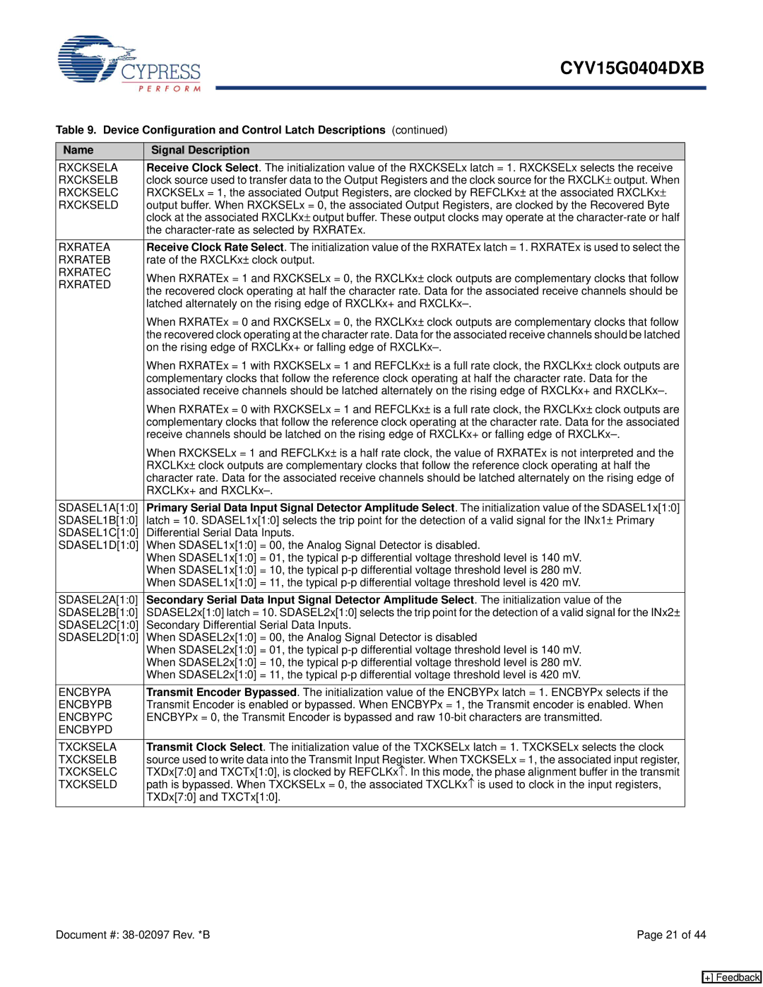
Table 9. Device Configuration and Control Latch Descriptions (continued) | |||||
|
|
| |||
Name | Signal Description |
|
| ||
RXCKSELA | Receive Clock Select. The initialization value of the RXCKSELx latch = 1. RXCKSELx selects the receive |
|
| ||
RXCKSELB | clock source used to transfer data to the Output Registers and the clock source for the RXCLK± output. When |
| |||
RXCKSELC | RXCKSELx = 1, the associated Output Registers, are clocked by REFCLKx± at the associated RXCLKx± |
| |||
RXCKSELD | output buffer. When RXCKSELx = 0, the associated Output Registers, are clocked by the Recovered Byte |
| |||
| clock at the associated RXCLKx± output buffer. These output clocks may operate at the |
| |||
| the |
| |||
RXRATEA | Receive Clock Rate Select. The initialization value of the RXRATEx latch = 1. RXRATEx is used to select the |
|
| ||
RXRATEB | rate of the RXCLKx± clock output. |
| |||
RXRATEC | When RXRATEx = 1 and RXCKSELx = 0, the RXCLKx± clock outputs are complementary clocks that follow |
|
| ||
RXRATED |
| ||||
the recovered clock operating at half the character rate. Data for the associated receive channels should be |
|
| |||
|
| ||||
| latched alternately on the rising edge of RXCLKx+ and |
| |||
| When RXRATEx = 0 and RXCKSELx = 0, the RXCLKx± clock outputs are complementary clocks that follow |
| |||
| the recovered clock operating at the character rate. Data for the associated receive channels should be latched |
| |||
| on the rising edge of RXCLKx+ or falling edge of |
| |||
| When RXRATEx = 1 with RXCKSELx = 1 and REFCLKx± is a full rate clock, the RXCLKx± clock outputs are |
| |||
| complementary clocks that follow the reference clock operating at half the character rate. Data for the |
| |||
| associated receive channels should be latched alternately on the rising edge of RXCLKx+ and |
| |||
| When RXRATEx = 0 with RXCKSELx = 1 and REFCLKx± is a full rate clock, the RXCLKx± clock outputs are |
| |||
| complementary clocks that follow the reference clock operating at the character rate. Data for the associated |
| |||
| receive channels should be latched on the rising edge of RXCLKx+ or falling edge of |
| |||
| When RXCKSELx = 1 and REFCLKx± is a half rate clock, the value of RXRATEx is not interpreted and the |
| |||
| RXCLKx± clock outputs are complementary clocks that follow the reference clock operating at half the |
| |||
| character rate. Data for the associated receive channels should be latched alternately on the rising edge of |
| |||
| RXCLKx+ and |
| |||
SDASEL1A[1:0] | Primary Serial Data Input Signal Detector Amplitude Select. The initialization value of the SDASEL1x[1:0] |
|
| ||
SDASEL1B[1:0] | latch = 10. SDASEL1x[1:0] selects the trip point for the detection of a valid signal for the INx1± Primary |
| |||
SDASEL1C[1:0] | Differential Serial Data Inputs. |
| |||
SDASEL1D[1:0] | When SDASEL1x[1:0] = 00, the Analog Signal Detector is disabled. |
| |||
| When SDASEL1x[1:0] = 01, the typical |
| |||
| When SDASEL1x[1:0] = 10, the typical |
| |||
| When SDASEL1x[1:0] = 11, the typical |
| |||
SDASEL2A[1:0] | Secondary Serial Data Input Signal Detector Amplitude Select. The initialization value of the |
|
| ||
SDASEL2B[1:0] | SDASEL2x[1:0] latch = 10. SDASEL2x[1:0] selects the trip point for the detection of a valid signal for the INx2± |
| |||
SDASEL2C[1:0] | Secondary Differential Serial Data Inputs. |
| |||
SDASEL2D[1:0] | When SDASEL2x[1:0] = 00, the Analog Signal Detector is disabled |
| |||
| When SDASEL2x[1:0] = 01, the typical |
| |||
| When SDASEL2x[1:0] = 10, the typical |
| |||
| When SDASEL2x[1:0] = 11, the typical |
| |||
ENCBYPA | Transmit Encoder Bypassed. The initialization value of the ENCBYPx latch = 1. ENCBYPx selects if the |
|
| ||
ENCBYPB | Transmit Encoder is enabled or bypassed. When ENCBYPx = 1, the Transmit encoder is enabled. When |
| |||
ENCBYPC | ENCBYPx = 0, the Transmit Encoder is bypassed and raw |
| |||
ENCBYPD |
|
|
|
|
|
TXCKSELA | Transmit Clock Select. The initialization value of the TXCKSELx latch = 1. TXCKSELx selects the clock |
|
| ||
TXCKSELB | source used to write data into the Transmit Input Register. When TXCKSELx = 1, the associated input register, |
| |||
TXCKSELC | TXDx[7:0] and TXCTx[1:0], is clocked by REFCLKx↑. In this mode, the phase alignment buffer in the transmit |
| |||
TXCKSELD | path is bypassed. When TXCKSELx = 0, the associated TXCLKx↑ is used to clock in the input registers, |
| |||
| TXDx[7:0] and TXCTx[1:0]. |
| |||
Document #: | Page 21 of 44 |
[+] Feedback