CYV15G0404DXB
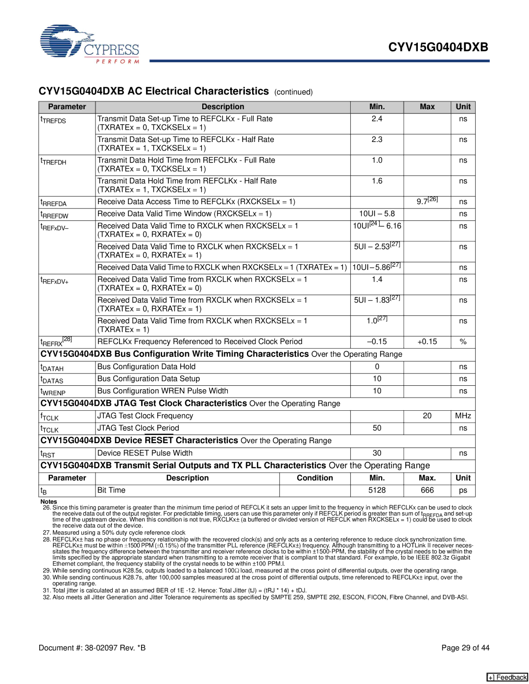
CYV15G0404DXB AC Electrical Characteristics (continued)
Parameter |
|
| Description |
| Min. | Max | Unit | |
tTREFDS | Transmit Data |
| 2.4 |
| ns | |||
| (TXRATEx = 0, TXCKSELx = 1) |
|
|
|
| |||
| Transmit Data |
| 2.3 |
| ns | |||
| (TXRATEx = 1, TXCKSELx = 1) |
|
|
|
| |||
tTREFDH | Transmit Data Hold Time from REFCLKx - Full Rate |
| 1.0 |
| ns | |||
| (TXRATEx = 0, TXCKSELx = 1) |
|
|
|
| |||
| Transmit Data Hold Time from REFCLKx - Half Rate |
| 1.6 |
| ns | |||
| (TXRATEx = 1, TXCKSELx = 1) |
|
|
|
| |||
tRREFDA | Receive Data Access Time to REFCLKx (RXCKSELx = 1) |
|
| 9.7[26] | ns | |||
tRREFDW | Receive Data Valid Time Window (RXCKSELx = 1) |
| 10UI – 5.8 |
| ns | |||
tREFxDV– | Received Data Valid Time to RXCLK when RXCKSELx = 1 | 10UI[24 ]– 6.16 |
| ns | ||||
| (TXRATEx = 0, RXRATEx = 0) |
|
|
|
| |||
| Received Data Valid Time to RXCLK when RXCKSELx = 1 | 5UI – 2.53[27] |
| ns | ||||
| (TXRATEx = 0, RXRATEx = 1) |
|
|
|
| |||
| Received Data Valid Time to RXCLK when RXCKSELx = 1 (TXRATEx = 1) | 10UI – 5.86[27] |
| ns | ||||
tREFxDV+ | Received Data Valid Time from RXCLK when RXCKSELx = 1 | 1.4 |
| ns | ||||
| (TXRATEx = 0, RXRATEx = 0) |
|
|
|
| |||
| Received Data Valid Time from RXCLK when RXCKSELx = 1 | 5UI – 1.83[27] |
| ns | ||||
| (TXRATEx = 0, RXRATEx = 1) |
|
|
|
| |||
| Received Data Valid Time from RXCLK when RXCKSELx = 1 | 1.0[27] |
| ns | ||||
| (TXRATEx = 1) |
|
|
|
| |||
tREFRX[28] | REFCLKx Frequency Referenced to Received Clock Period | +0.15 | % | |||||
CYV15G0404DXB | Bus Configuration Write Timing Characteristics Over the | Operating Range |
|
| ||||
tDATAH | Bus Configuration Data Hold |
| 0 |
| ns | |||
tDATAS | Bus Configuration Data Setup |
| 10 |
| ns | |||
tWRENP | Bus Configuration WREN Pulse Width |
| 10 |
| ns | |||
CYV15G0404DXB | JTAG Test Clock Characteristics Over the Operating Range |
|
|
| ||||
fTCLK | JTAG Test Clock Frequency |
|
| 20 | MHz | |||
tTCLK | JTAG Test Clock Period |
| 50 |
| ns | |||
CYV15G0404DXB | Device | RESET | Characteristics Over the Operating Range |
|
|
| ||
tRST | Device RESET Pulse Width |
| 30 |
| ns | |||
CYV15G0404DXB | Transmit Serial Outputs and TX PLL Characteristics Over | the Operating | Range |
| ||||
Parameter |
| Description |
| Condition | Min. | Max. | Unit | |
tB | Bit Time |
|
| 5128 | 666 | ps | ||
Notes
26.Since this timing parameter is greater than the minimum time period of REFCLK it sets an upper limit to the frequency in which REFCLKx can be used to clock the receive data out of the output register. For predictable timing, users can use this parameter only if REFCLK period is greater than sum of tRREFDA and
27.Measured using a 50% duty cycle reference clock
28.REFCLKx± has no phase or frequency relationship with the recovered clock(s) and only acts as a centering reference to reduce clock synchronization time. REFCLKx± must be within ±1500 PPM (±0.15%) of the transmitter PLL reference (REFCLKx±) frequency. Although transmitting to a HOTLink II receiver neces- sitates the frequency difference between the transmitter and receiver reference clocks to be within
29.While sending continuous K28.5s, outputs loaded to a balanced 100Ω load, measured at the cross point of differential outputs, over the operating range.
30.While sending continuous K28.7s, after 100,000 samples measured at the cross point of differential outputs, time referenced to REFCLKx± input, over the operating range.
31.Total jitter is calculated at an assumed BER of 1E
32.Also meets all Jitter Generation and Jitter Tolerance requirements as specified by SMPTE 259, SMPTE 292, ESCON, FICON, Fibre Channel, and
Document #: | Page 29 of 44 |
[+] Feedback