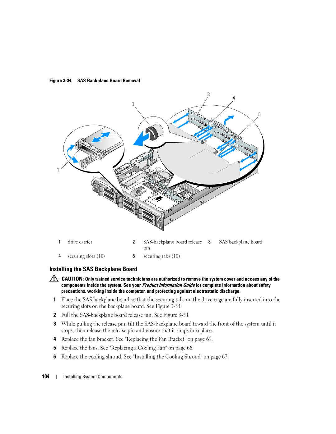
Figure 3-34. SAS Backplane Board Removal
3
2
1
4
5
1 | drive carrier | 2 |
| SAS backplane board |
|
|
| pin |
|
4 | securing slots (10) | 5 | securing tabs (10) |
|
Installing the SAS Backplane Board
CAUTION: Only trained service technicians are authorized to remove the system cover and access any of the components inside the system. See your Product Information Guide for complete information about safety precautions, working inside the computer, and protecting against electrostatic discharge.
1Place the SAS backplane board so that the securing tabs on the drive cage are fully inserted into the securing slots on the backplane board. See Figure
2Pull the
3While pulling the release pin, tilt the
4Replace the fan bracket. See "Replacing the Fan Bracket" on page 69.
5Replace the fans. See "Replacing a Cooling Fan" on page 66.
6Replace the cooling shroud. See "Installing the Cooling Shroud" on page 67.
104