Dell PowerEdge T105 Systems Hardware Owner’s Manual
w w w . d e l l . c o m s u p p o r t . d e l l . c o m
March
Notes, Notices, and Cautions
P/N JN551
Contents
2 Using the System Setup Program
3 Installing System Components
System and Setup Password Features
Addressing Memory With 8-GB Configurations
Chassis Intrusion Switch
4 Troubleshooting Your System
Power Supply
Procedure
Troubleshooting an External SCSI Tape Drive
5 Running the System Diagnostics
Troubleshooting System Cooling Problems
Troubleshooting a SAS or SAS RAID Controller
Returning Items for Warranty Repair or Credit
6 Jumpers and Connectors
Dell Enterprise Training and Certification
Glossary Index
Contents
About Your System
Other Information You May Need
Accessing System Features During Startup
Front-Panel Features and Indicators
NOTE If you turn off the system using
serial connector
Back-Panel Features and Indicators
power connector
Figure 1-3. NIC Indicators
Connecting External Devices
NIC Indicator Codes
activity indicator
program. See Using the System Setup Program
Power Supply Indicators
When off at the same time that the link indicator
indicator is off, the NIC is not connected to the
Corrective Action
Diagnostic Lights
See Troubleshooting Expansion
The system is in a normal
Table 1-5. Diagnostic Indicator Codes continued
System Messages
Alert! Incompatible
Bad error-correction
processor cooling shroud
Table 1-6. System Messages continued
Not a boot diskette
No timer tick interrupt
error
restore system resources
Table 1-6. System Messages continued
Table 1-6. System Messages continued
The amount of system
Time-of-day not set - please run SETUP program
Timer chip counter
memory has changed
Warning Messages
drive letter\ is not
Diagnostics Messages
Alert Messages
Entering the System Setup Program
Using the System Setup Program
Responding to Error Messages
or confirm your setting change and move the cursor
Using the System Setup Program
Cycles through the settings in a field. In many fields
Displays the System Setup programs help file for the
System Setup Options
Exiting the System Setup Program
Main Screen
Attachment SATA device such as hard drive, CD drive
Memory Information Screen
SATA Configuration Screen
CPU Information Screen
device attached to Port A. When set to Auto default, the
Integrated Devices Screen
ATA Mode. Off disables the SATA subsystem. ATA Mode
device attached to Port B. When set to Auto default, the
System Security Screen
System and Setup Password Features
Exit Screen
Using the System Password
4 Press Enter
Using the Setup Password
Disabling a Forgotten Password
Using the System Setup Program
Installing System Components
Recommended Tools
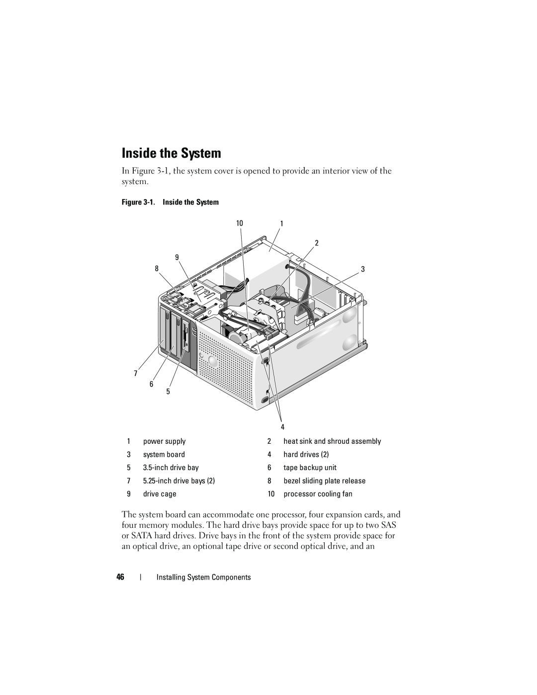
Inside the System
heat sink and shroud assembly
Opening the System
Closing the System
Front Drive Bezel
Removing the Front Drive Bezel
Replacing the Front Drive Bezel
Replacing an Insert on the Front Drive Bezel
Removing an Insert on the Front Drive Bezel
front drive bezel
Removing and Inserting Blank Drive Inserts
drive bezel insert
Diskette Drive
Removing the Diskette Drive
6 Hold the lever in position and slowly pull the drive out of the bay
Installing a Diskette Drive
10 Connect the P7 power cable to the drive. See Figure
13 Close the system. See Closing the System on page
Optical and Tape Drives
Removing an Optical or Tape Drive
optical drive
optical drive shoulder screw
10 Close the system. See Closing the System on page
Installing an Optical or Tape Drive
7 Remove the three shoulder screws from the insert, and attach one of them to the row of holes and two to the bottom row of holes on the drive. See Figure
SCSI card
SCSI connector
Figure 3-12. Cabling SCSI to the Optical Disk Drive
optical disk drive
optical disk drive
Hard Drives
Hard Drive Installation Guidelines
Removing a Hard Drive
hard drive in primary hard drive bay
Installing a Hard Drive
8 Connect the power cable to the hard drive
SATAB data cable to system board
SATAA data cable to system board
10 Ensure that all connectors are properly cabled and firmly seated
Expansion Cards
Removing an Expansion Card
5 Grasp the card by its top corners and ease it out of its connector
Installing an Expansion Card
SAS Controller Expansion Card
clip on hard disk drive fan shroud
retaining tabs on top of heat sink
top notch on heat sink fan shroud
Memory Module Installation Guidelines
Memory Module Upgrade Kits
Memory
The following components require address space System ROM
Installing a Memory Module
Removing a Memory Module
memory module socket ejectors
Microprocessor
Removing the Processor
Page
captive screws
Figure 3-21. Installing and Removing the Heat Sink
heat sink and shroud assembly
pivot bracket
Replacing the Processor
Cooling Fans
Removing the Cooling Fans
top release tabs
Figure 3-23. Removing and Installing the SAS Controller Cooling Fan
bottom connectors
cooling fan
Replacing the Cooling Fans
bottom mounting holes
If you are replacing the hard drive cooling fan
System Battery
fan connector cable
Removing the System Battery
Installing the System Battery
Power Supply
Removing the Power Supply
power supply
Installing the Power Supply
Chassis Intrusion Switch
Removing the Chassis Intrusion Switch
Installing the Chassis Intrusion Switch
Bezel Service Only Parts Procedure
Removing the Bezel
Replacing the Bezel
alignment slot
I/O Panel Assembly Service Only Parts Procedure
Removing the I/O Panel Assembly
Replacing the I/O Panel Assembly
I/O panel securing slot
2 Secure the I/O panel assembly by replacing the screw. See Figure
System Board Service Only Parts Procedure
Removing the System Board
Installing the System Board
Two power-supply cables to the POWER and POWER12V1 connectors
Safety First-For You and Your System
Troubleshooting Your System
Start-Up Routine
Troubleshooting the Video Subsystem
Troubleshooting External Connections
Checking the Equipment
Troubleshooting the Keyboard
Troubleshooting the Mouse
Troubleshooting Serial I/O Problems
Troubleshooting a Serial I/O Device
Troubleshooting a USB Device
Troubleshooting a NIC
Troubleshooting a Wet System
Troubleshooting a Damaged System
Troubleshooting the System Battery
Troubleshooting Power Supply
Troubleshooting System Cooling Problems
Troubleshooting a Fan
Troubleshooting System Memory
6 Open the system. See Opening the System on page
Troubleshooting a Diskette Drive
5 Open the system. See Opening the System on page
Troubleshooting an Optical Drive
Troubleshooting an External SCSI Tape Drive
Troubleshooting a Hard Drive
6 Check the cable connections inside the system
Troubleshooting a SAS or SAS RAID Controller
Troubleshooting Expansion Cards
4 Open the system. See Opening the System on page
Troubleshooting the Microprocessor
12 Reconnect the system to the electrical outlet, and turn on the system and attached peripherals
Using Dell PowerEdge Diagnostics
Running the System Diagnostics
System Diagnostics Features
Running the System Diagnostics
When to Use the System Diagnostics
System Diagnostics Testing Options
Selecting Devices for Testing
Using the Custom Test Options
Selecting Diagnostics Options
Viewing Information and Results
Jumpers and Connectors
System Board Jumpers
The configuration settings in NVRAM are cleared
System Board Connectors
32-bit, 33-MHz PCI
Disabling a Forgotten Password
Jumpers and Connectors
Getting Help
Obtaining Assistance
Online Services
Support Service
Problems With Your Order
Automated Order-Status Service
Dell Enterprise Training and Certification
Returning Items for Warranty Repair or Credit
Before You Call
Diagnostics Checklist Name Date Address Phone number
Contacting Dell
Transaction Sales Xiamen
Country City
Country City
BRTechSupport@dell.com
Country City
support.ca.dell.com
Canada North York
Ontario
1 866 440
Technical Support - Dell
Country City
Country City
Country City
Sales under 500 employees
Country City
Country City
Medium Business Division
Projectors, PDAs, Switches
Global Customer Programs
Home and Small Business
Country City
Country City
Country City
Country City
Country City
Country City
Country City
Country City
Country City
Country City
800 300 410 or 800 300
support.ap.dell.com
Country City
Country City
Country City
Getting Help
Glossary
bus - An information pathway between the components of a system. Your system contains an expansion bus that allows the processor to communicate with controllers for the peripheral devices connected to the system. Your system also contains an address bus and a data bus for communications between the processor and RAM
directory - Directories help keep related files organized on a disk in a hierarchical, “inverted tree” structure. Each disk has a “root” directory. Additional directories that branch off the root directory are called subdirectories. Subdirectories may contain additional directories branching off them
GB - Gigabytes 1024 megabytes or 1,073,741,824 bytes. However, when referring to hard-drive capacity, the term is usually rounded to 1,000,000,000 bytes
Page
Page
Page
A memory address space of 16 MB to 4 GB Multitasking
SVGA - Super video graphics array. VGA and SVGA are video standards for video adapters with greater resolution and color display capabilities than previous standards
system memory - See RAM
video adapter - The logical circuitry that provides in combination with the monitor your system’s video capabilities. A video adapter may be integrated into the system board or may be an expansion card that plugs into an expansion slot
Glossary
Index
Numbers
Page
Page
Page