2.2.1 Attach Jackrabbit to Prototyping Board
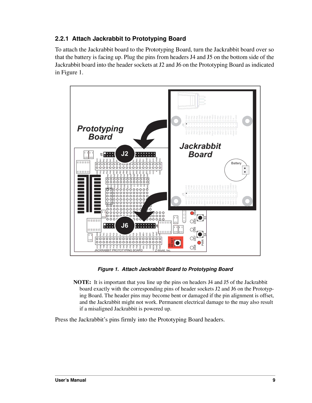
To attach the Jackrabbit board to the Prototyping Board, turn the Jackrabbit board over so that the battery is facing up. Plug the pins from headers J4 and J5 on the bottom side of the Jackrabbit board into the header sockets at J2 and J6 on the Prototyping Board as indicated in Figure 1.
Prototyping |
|
|
|
|
|
|
|
|
|
|
| ||||||||
Board |
|
|
|
|
|
|
|
|
|
|
|
|
|
|
| ||||
| J2 |
|
|
|
|
| J2 | PCLK |
|
|
|
|
|
|
| +RAW |
| ||
VCC | PA1 | PA3 | PA5 | PA7 | GND | PB1 | PB3 | PB5 | PB7 | PE7 | PE5 | PE3 | PE1 | GND | HV1 | HV3 | VCC | ||
GND | PA0 | PA2 | PA4 | PA6 | GND | PB0 | PB2 | PB4 | PB6 | WDO | GND | PE6 | PE4 | PE2 | PE0 | HV0 | HV2 | K | GND |
PA0 | PA1 | PA2 | PA3 | PA4 | PA5 | PA6 | PA7 | PB2 | PB3 | PB4 | PB5 | GND | |||||||
|
|
| DS1 | DS2 | DS3 | DS4 | DS5 | DS6 | DS7 | DS8 | S1 | S2 | S3 | S4 | GND |
|
|
|
|
|
|
|
|
|
|
|
| J6 |
|
|
|
|
|
|
|
| J6 |
|
| |
GND | RXC | TXC | PC1 | PC3 | PC5 | PC7 | AGND | DA1 | PD1 | PD3 | PD5 | PD7 | GND | 485+ | VCC | SM1 | STAT | VBAT | GND |
|
VCC | RXB | TXB | PC0 | PC2 | PC4 | PC6 | AD0 | DA0 | PD0 | PD2 | PD4 | PD6 | GND | 485– | VCC | SM0 | IOBEN | GND | /RST | S5 RESET |
JACKRABBIT PROTOTYPING BOARD |
|
|
|
| ||||||||||||||||
GND PA0 PA2 PA4 PA6 GND PB0 PB2 PB4 PB6 WDO GND PE6 PE4 PE2 PE0 HV0 HV2 K GND
J4 VCC PA1 PA3 PA5 PA7 GND PB1 PB3 PB5 PB7 PCLK PE7 PE5 PE3 PE1 GND HV1 HV3 +RAW VCC
Jackrabbit |
| |
Board |
| |
| R3 |
|
Buzzer | + |
|
| Battery | |
|
| |
VCC RXB TXB PC0DS1 PC2 PC4 PC6 AD0S1 DA0 PD0 PD2 PD4 PD6 GND 485– VCC SM0 IOBEN GND /RST | ||
J5 |
|
| DS3PC1 |
|
| S2AGND |
|
|
|
|
|
|
|
|
|
|
|
|
GND | RXC | TXC | PC5 | PC7 | DA1 | PD1 | PD3 | PD5 | PD7 | GND | 485+ | VCC | SM1 | STAT | VBAT | GND | ||
|
|
| PC3 |
|
|
|
|
|
|
|
|
|
|
|
|
|
|
|
DS4 |
|
DS5 | S3 |
DS6 |
|
DS8 DS7 | S4 |
PWR |
Figure 1. Attach Jackrabbit Board to Prototyping Board
NOTE: It is important that you line up the pins on headers J4 and J5 of the Jackrabbit board exactly with the corresponding pins of header sockets J2 and J6 on the Prototyp- ing Board. The header pins may become bent or damaged if the pin alignment is offset, and the Jackrabbit might not work. Permanent electrical damage to the may also result if a misaligned Jackrabbit is powered up.
Press the Jackrabbit’s pins firmly into the Prototyping Board headers.
User’s Manual | 9 |