3.7 Memory
3.7.1 SRAM
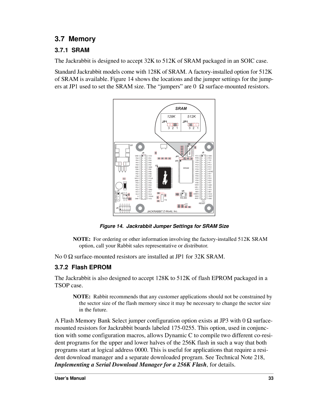
The Jackrabbit is designed to accept 32K to 512K of SRAM packaged in an SOIC case.
Standard Jackrabbit models come with 128K of SRAM. A
U1 |
GND | J1 |
J2 | |
VIN GND |
|
J3 ![]()
![]()
![]()
![]()
|
|
|
| SRAM |
|
|
| |
|
| 128K | 512K |
| ||||
|
| JP1 |
|
| JP1 |
|
|
|
|
| 3 | 2 | 1 | 3 | 2 | 1 |
|
|
|
|
|
| U4 |
|
|
|
| J4 |
|
|
|
|
| J5 | |
GND | VCC |
|
| JP1 |
|
| VCC | GND |
PA0 | PA1 |
|
|
|
| RXB | RXC | |
|
|
|
|
| ||||
PA2 | PA3 |
|
| U5 |
|
| TXB | TXC |
PA4 | PA5 |
|
|
|
|
| PC0 | PC1 |
PA6 | PA7 | U3 |
|
|
|
| PC2 | PC3 |
GND | GND |
|
|
|
| PC4 | PC5 | |
|
|
| SRAM |
| ||||
PB0 | PB1 |
|
|
|
| PC6 | PC7 | |
|
|
|
|
| ||||
PB2 | PB3 |
|
|
|
|
| AD0 | AGND |
PB4 | PB5 |
|
|
|
|
| DA0 | DA1 |
PB6 | PB7 |
|
|
|
|
| PD0 | PD1 |
WDO | PCLK |
|
|
|
|
| PD2 | PD3 |
GND | PE7 |
|
|
|
|
| PD4 | PD5 |
PE6 | PE5 |
|
|
|
|
| PD6 | PD7 |
PE4 | PE3 |
|
|
|
|
| GND | GND |
PE2 | PE1 |
|
|
|
|
| 485– | 485+ |
PE0 | GND |
|
|
| U6 |
| VCC | VCC |
HV0 | HV1 |
|
|
|
| SM0 | SM1 | |
HV2 | HV3 |
|
|
|
| IOBEN | STAT | |
K | +RAW |
|
|
|
| GND | VBAT | |
GND | VCC | Y3 |
|
|
| /RST | GND | |
|
|
|
|
|
|
|
| |
|
|
|
|
|
|
|
| RESET |
JACKRABBIT
Figure 14. Jackrabbit Jumper Settings for SRAM Size
NOTE: For ordering or other information involving the
No 0 Ω
3.7.2 Flash EPROM
The Jackrabbit is also designed to accept 128K to 512K of flash EPROM packaged in a TSOP case.
NOTE: Rabbit recommends that any customer applications should not be constrained by the sector size of the flash memory since it may be necessary to change the sector size in the future.
A Flash Memory Bank Select jumper configuration option exists at JP3 with 0 Ω surface- mounted resistors for Jackrabbit boards labeled
User’s Manual | 33 |