2.2.2 Connect Programming Cable
The programming cable connects the Jackrabbit to the PC running Dynamic C to down- load programs and to monitor the Jackrabbit during debugging.
Connect the
NOTE: Use only the programming cable that has a red shrink wrap around the
1Remove slot cover, insert tab into slot
Assemble
AC Adapter
2 Snap plug into place
JACKRABBIT BOARD
U1 |
GND | J1 |
J2 | |
GND |
|
J3 ![]()
![]()
![]()
![]()
Colored side |
|
lines up with | PROG |
pin 1 | |
Programming |
|
connector |
|
Diagnostic | DIAG |
connector |
|
|
| U4 |
|
| |
|
|
| J5 | ||
| J4 | RS |
| ||
| VCC | GND | |||
GND | VCC | JP1 | |||
PA0 | PA1 |
| RXB | RXC | |
PA2 | PA3 | U5 | TXB | TXC | |
PA4 | PA5 |
| PC0 | PC1 | |
PA6 | PA7 | U3 | PC2 | PC3 | |
GND | GND | PC4 | PC5 | ||
SRAM | |||||
PB0 | PB1 | PC6 | PC7 | ||
| |||||
PB2 | PB3 |
| AD0 | AGND | |
PB4 | PB5 | Rabbit 2000 | DA0 | DA1 | |
PB6 | PB7 | PD0 | PD1 | ||
| |||||
WDO | PCLK |
| PD2 | PD3 | |
GND | PE7 |
| PD4 | PD5 | |
PE6 | PE5 |
| PD6 | PD7 | |
PE4 | PE3 |
| GND | GND | |
PE2 | PE1 |
| 485– | 485+ | |
PE0 | GND | U6 | VCC | VCC | |
HV0 | HV1 | SM0 | SM1 | ||
HV2 | HV3 |
| IOBEN | STAT | |
K | +RAW | GND | VBAT | ||
GND | VCC | /RST | GND | ||
|
| Y3 |
|
|
RESET
JACKRABBIT
PROTOTYPING BOARD
Red
![]() shrink wrap
shrink wrap
To
PC COM port
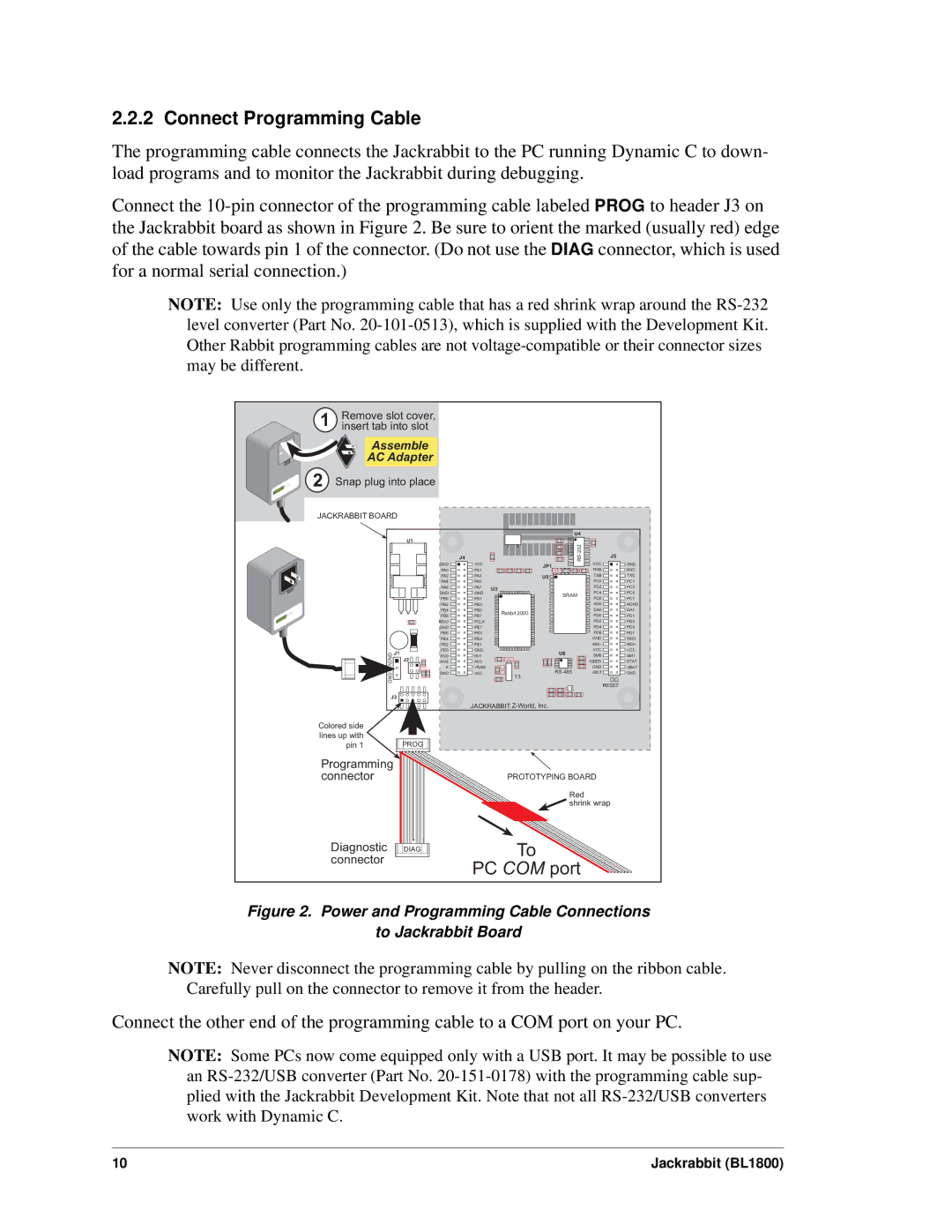
Figure 2. Power and Programming Cable Connections
to Jackrabbit Board
NOTE: Never disconnect the programming cable by pulling on the ribbon cable. Carefully pull on the connector to remove it from the header.
Connect the other end of the programming cable to a COM port on your PC.
NOTE: Some PCs now come equipped only with a USB port. It may be possible to use an
10 | Jackrabbit (BL1800) |