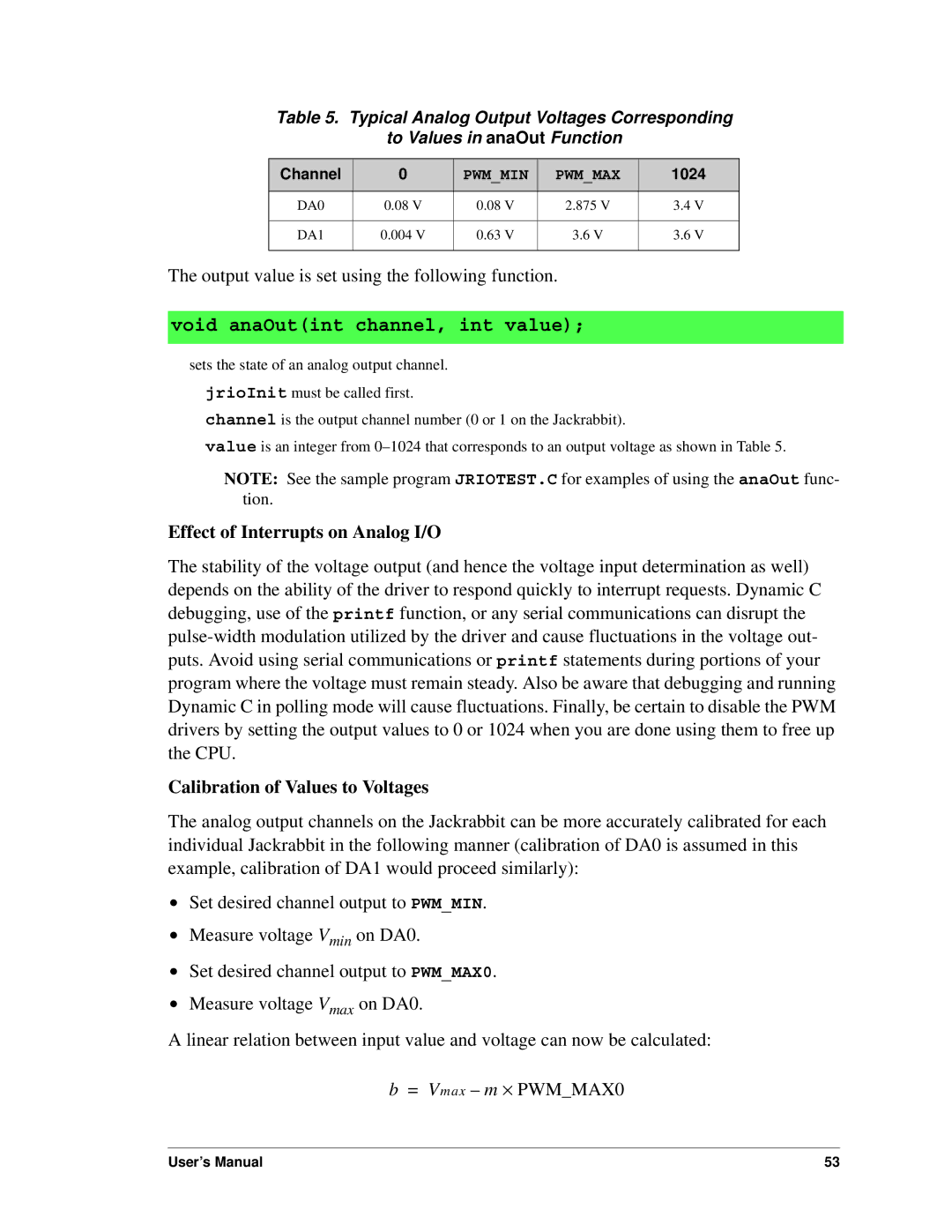
Table 5. Typical Analog Output Voltages Corresponding
to Values in anaOut Function
Channel | 0 | PWM_MIN | PWM_MAX | 1024 |
|
|
|
|
|
DA0 | 0.08 V | 0.08 V | 2.875 V | 3.4 V |
|
|
|
|
|
DA1 | 0.004 V | 0.63 V | 3.6 V | 3.6 V |
|
|
|
|
|
The output value is set using the following function.
void anaOut(int channel, int value);
sets the state of an analog output channel. jrioInit must be called first.
channel is the output channel number (0 or 1 on the Jackrabbit).
value is an integer from
NOTE: See the sample program JRIOTEST.C for examples of using the anaOut func- tion.
Effect of Interrupts on Analog I/O
The stability of the voltage output (and hence the voltage input determination as well) depends on the ability of the driver to respond quickly to interrupt requests. Dynamic C debugging, use of the printf function, or any serial communications can disrupt the
Calibration of Values to Voltages
The analog output channels on the Jackrabbit can be more accurately calibrated for each individual Jackrabbit in the following manner (calibration of DA0 is assumed in this example, calibration of DA1 would proceed similarly):
•Set desired channel output to PWM_MIN.
•Measure voltage Vmin on DA0.
•Set desired channel output to PWM_MAX0.
•Measure voltage Vmax on DA0.
A linear relation between input value and voltage can now be calculated:
b = Vmax – m ⋅ PWM_MAX0
User’s Manual | 53 |
