3.6 Programming Cable
The programming cable is used to connect the Jackrabbit’s programming port to a PC serial COM port. The programming cable converts the
When the PROG connector on the programming cable is connected to the Jackrabbit’s programming header, programs can be downloaded and debugged over the serial interface.
The DIAG connector of the programming cable may be used on the Jackrabbit’s program- ming header with the Jackrabbit operating in the Run Mode. This allows the programming port to be used as a regular serial port.
3.6.1 Changing Between Program Mode and Run Mode
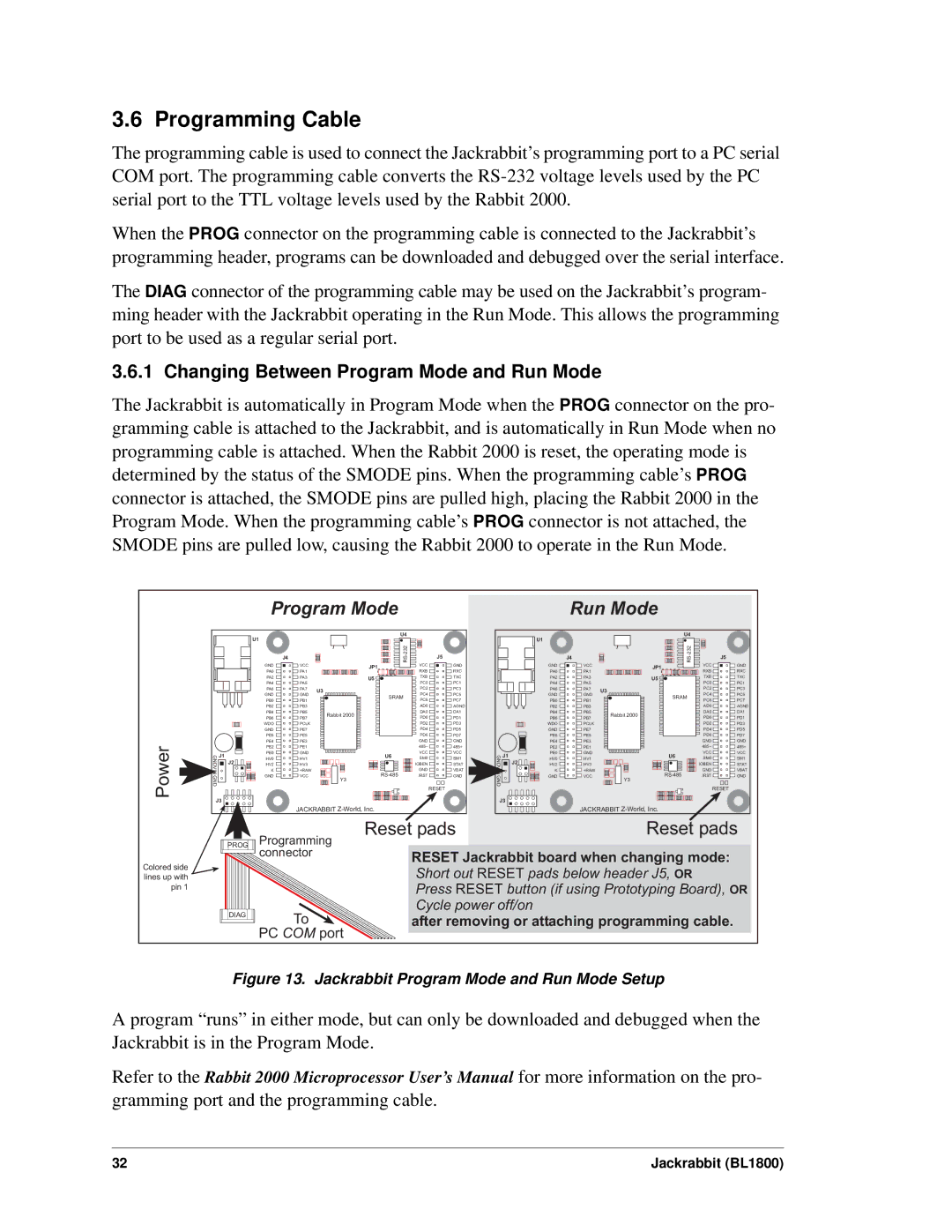
The Jackrabbit is automatically in Program Mode when the PROG connector on the pro- gramming cable is attached to the Jackrabbit, and is automatically in Run Mode when no programming cable is attached. When the Rabbit 2000 is reset, the operating mode is determined by the status of the SMODE pins. When the programming cable’s PROG connector is attached, the SMODE pins are pulled high, placing the Rabbit 2000 in the Program Mode. When the programming cable’s PROG connector is not attached, the SMODE pins are pulled low, causing the Rabbit 2000 to operate in the Run Mode.
Program Mode | Run Mode |
Power
U1 |
GND | J1 |
J2 | |
GND |
|
| J4 |
| |
GND | VCC |
| |
PA0 | PA1 |
| |
PA2 | PA3 |
| |
PA4 | PA5 |
| |
PA6 | PA7 | U3 | |
GND | GND | ||
| |||
PB0 | PB1 |
| |
PB2 | PB3 |
| |
PB4 | PB5 | Rabbit 2000 | |
PB6 | PB7 | ||
| |||
WDO | PCLK |
| |
GND | PE7 |
| |
PE6 | PE5 |
| |
PE4 | PE3 |
| |
PE2 | PE1 |
| |
PE0 | GND |
| |
HV0 | HV1 |
| |
HV2 | HV3 |
| |
K | +RAW |
| |
GND | VCC | Y3 | |
|
|
U4 |
|
| |
| J5 | ||
JP1 | VCC | GND | |
RXB | RXC | ||
| |||
U5 | TXB | TXC | |
| PC0 | PC1 | |
| PC2 | PC3 | |
SRAM | PC4 | PC5 | |
PC6 | PC7 | ||
| |||
| AD0 | AGND | |
| DA0 | DA1 | |
| PD0 | PD1 | |
| PD2 | PD3 | |
| PD4 | PD5 | |
| PD6 | PD7 | |
| GND | GND | |
| 485– | 485+ | |
U6 | VCC | VCC | |
SM0 | SM1 | ||
| IOBEN | STAT | |
GND | VBAT | ||
/RST | GND | ||
|
| RESET |
Colored side lines up with pin 1
J3 |
|
| J3 |
|
| JACKRABBIT |
| JACKRABBIT | |
| Programming | Reset pads | Reset pads | |
PROG |
|
|
| |
| connector |
| RESET Jackrabbit board when changing mode: | |
|
|
| Short out RESET pads below header J5, OR | |
|
|
| Press RESET button (if using Prototyping Board), OR | |
DIAG | To |
| Cycle power off/on |
|
| after removing or attaching programming cable. | |||
|
| |||
| PC COM port |
|
|
|
Figure 13. Jackrabbit Program Mode and Run Mode Setup
A program “runs” in either mode, but can only be downloaded and debugged when the Jackrabbit is in the Program Mode.
Refer to the Rabbit 2000 Microprocessor User’s Manual for more information on the pro- gramming port and the programming cable.
32 | Jackrabbit (BL1800) |