The
•It reduces the battery voltage to the
•It ensures that current can flow only out of the battery to prevent charging the battery.
C.2.2 Power to VRAM Switch
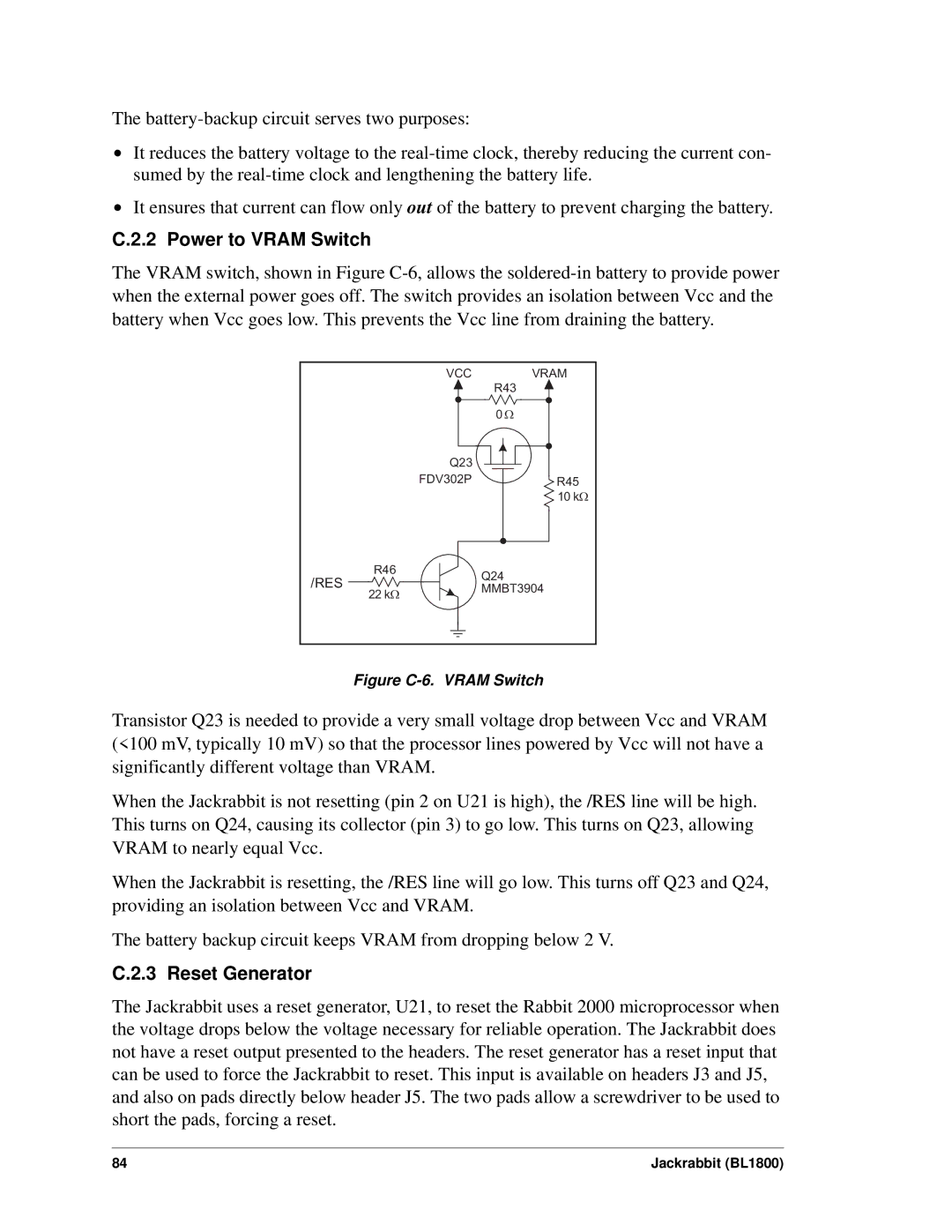
The VRAM switch, shown in Figure
VCC VRAM
R43
0 W
Q23
FDV302PR45 10 kW
/RES | R46 | Q24 | |
| |||
22 kW | MMBT3904 | ||
| |||
|
|
Figure C-6. VRAM Switch
Transistor Q23 is needed to provide a very small voltage drop between Vcc and VRAM (<100 mV, typically 10 mV) so that the processor lines powered by Vcc will not have a significantly different voltage than VRAM.
When the Jackrabbit is not resetting (pin 2 on U21 is high), the /RES line will be high. This turns on Q24, causing its collector (pin 3) to go low. This turns on Q23, allowing VRAM to nearly equal Vcc.
When the Jackrabbit is resetting, the /RES line will go low. This turns off Q23 and Q24, providing an isolation between Vcc and VRAM.
The battery backup circuit keeps VRAM from dropping below 2 V.
C.2.3 Reset Generator
The Jackrabbit uses a reset generator, U21, to reset the Rabbit 2000 microprocessor when the voltage drops below the voltage necessary for reliable operation. The Jackrabbit does not have a reset output presented to the headers. The reset generator has a reset input that can be used to force the Jackrabbit to reset. This input is available on headers J3 and J5, and also on pads directly below header J5. The two pads allow a screwdriver to be used to short the pads, forcing a reset.
84 | Jackrabbit (BL1800) |