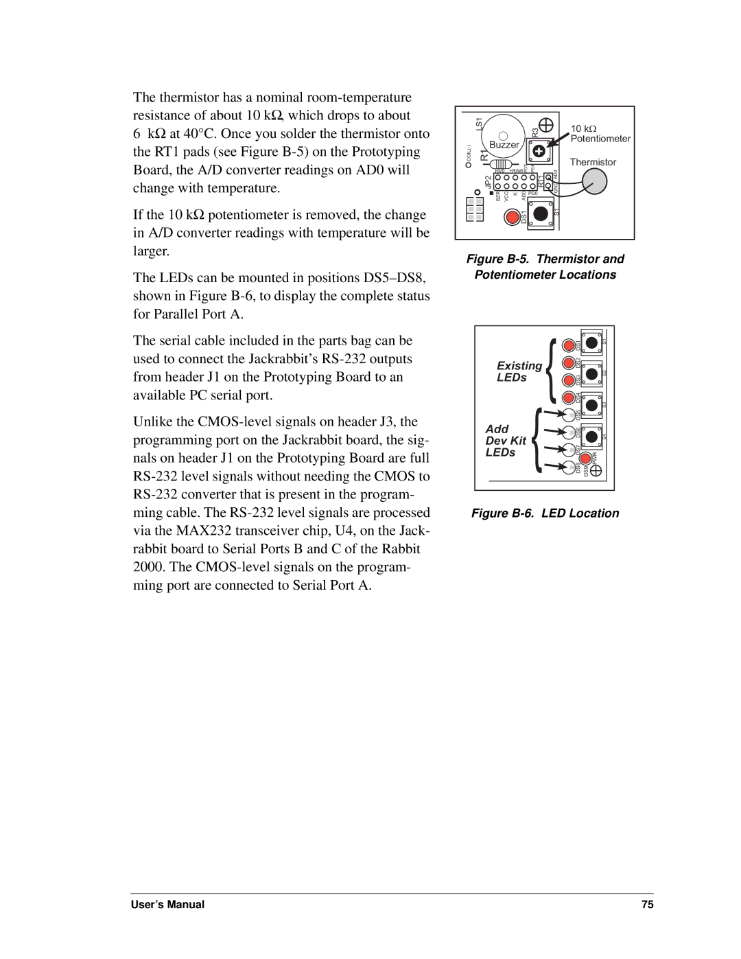
The thermistor has a nominal
6kΩ at 40°C. Once you solder the thermistor onto the RT1 pads (see Figure
If the 10 kΩ potentiometer is removed, the change in A/D converter readings with temperature will be larger.
| LS1 |
|
|
| R3 |
|
| Buzzer |
| 3 |
| ||
|
| 2 |
| |||
|
|
|
|
|
| |
COIL()- | R1 |
|
|
| + |
|
|
|
| 1 |
| ||
|
| HV0 | +RAWPOT PE4 | GND AD0 | ||
| JP2 |
|
|
| RT1 | |
| BZR VCC | K | AD0 | PD0 | ||
|
| |||||
|
|
|
| DS1 |
| S1 |
10kW Potentiometer
Thermistor
The LEDs can be mounted in positions
The serial cable included in the parts bag can be used to connect the Jackrabbit’s
Unlike the
Figure B-5. Thermistor and
Potentiometer Locations
|
| } | DS1 | S1 |
Existing |
| DS2 |
| |
LEDs | } |
| DS3 | S2 |
|
| |||
|
| DS4 | S3 | |
|
| DS5 |
| |
Add |
| DS6 |
| |
Dev Kit |
| S4 | ||
| DS8 DS7 DS9 |
| ||
LEDs |
| PWR | ||
|
|
| ||
Figure B-6. LED Location
User’s Manual | 75 |