3.4 D/A Converters
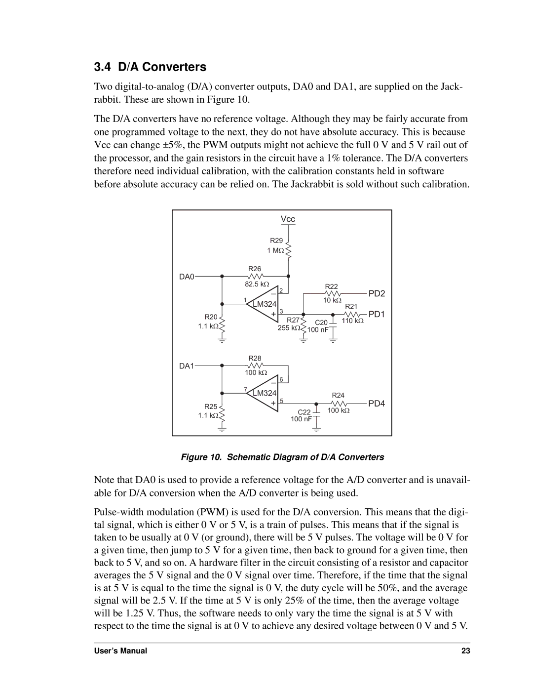
Two digital-to-analog (D/A) converter outputs, DA0 and DA1, are supplied on the Jack- rabbit. These are shown in Figure 10.
The D/A converters have no reference voltage. Although they may be fairly accurate from one programmed voltage to the next, they do not have absolute accuracy. This is because Vcc can change ±5%, the PWM outputs might not achieve the full 0 V and 5 V rail out of the processor, and the gain resistors in the circuit have a 1% tolerance. The D/A converters therefore need individual calibration, with the calibration constants held in software before absolute accuracy can be relied on. The Jackrabbit is sold without such calibration.
| | | Vcc | | | | |
| | R29 | | | | |
| | 1 MW | | | | |
| DA0 | R26 | | | | | |
| | | | | | |
| 82.5 kW | | | R22 | | |
| | – | 2 | | | PD2 |
| | | | |
| 1 | | | 10 kW | |
| | | | |
| LM324 | 3 | | R21 | |
| R20 | + | | | | PD1 |
| R27 | | C20 | 110 kW |
| 1.1 kW | | | |
| | 255 kW | 100 nF | | |
| DA1 | R28 | | | | | |
| | | | | | |
| 100 kW | | | | | |
| | – | 6 | | | | |
| | | | | | |
| 7 | LM324 | 5 | | R24 | |
| R25 | + | | | | PD4 |
| C22 | 100 kW |
| 1.1 kW | | |
| | 100 nF | | | |
| | | | | |
Figure 10. Schematic Diagram of D/A Converters
Note that DA0 is used to provide a reference voltage for the A/D converter and is unavail- able for D/A conversion when the A/D converter is being used.
Pulse-width modulation (PWM) is used for the D/A conversion. This means that the digi- tal signal, which is either 0 V or 5 V, is a train of pulses. This means that if the signal is taken to be usually at 0 V (or ground), there will be 5 V pulses. The voltage will be 0 V for a given time, then jump to 5 V for a given time, then back to ground for a given time, then back to 5 V, and so on. A hardware filter in the circuit consisting of a resistor and capacitor averages the 5 V signal and the 0 V signal over time. Therefore, if the time that the signal is at 5 V is equal to the time the signal is 0 V, the duty cycle will be 50%, and the average signal will be 2.5 V. If the time at 5 V is only 25% of the time, then the average voltage will be 1.25 V. Thus, the software needs to only vary the time the signal is at 5 V with respect to the time the signal is at 0 V to achieve any desired voltage between 0 V and 5 V.