Before running the LCD_DEMO.C sample program, you will need an LCD based on the HD44780 (or an equivalent) controller.
•
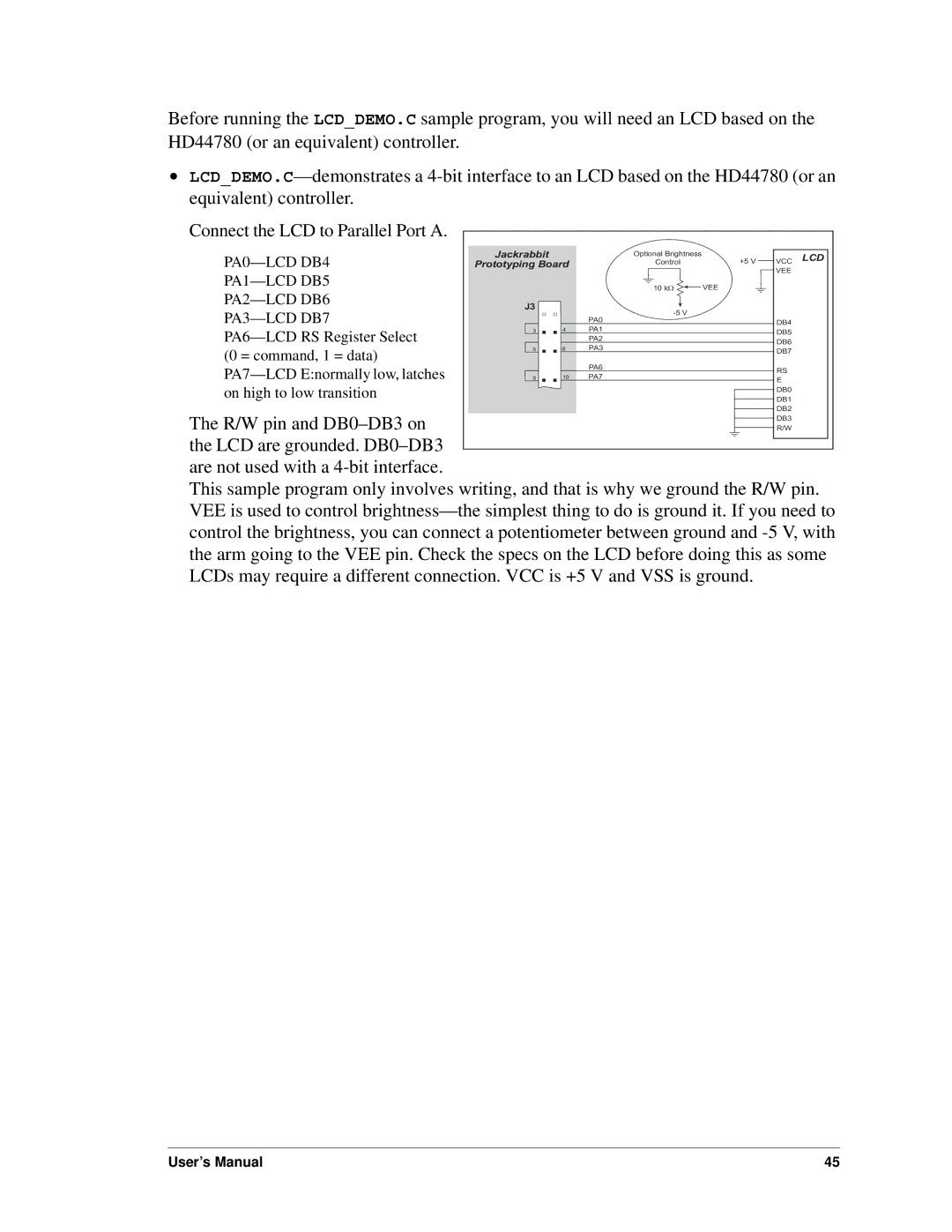
Connect the LCD to Parallel Port A. |
|
|
|
|
|
|
|
|
|
|
|
|
|
|
|
|
|
|
|
|
|
|
|
|
|
|
|
|
|
|
|
|
|
|
|
|
|
|
|
|
|
| |
|
|
|
|
|
|
|
|
|
|
|
|
|
|
|
|
|
|
|
|
|
|
| Jackrabbit |
| Optional Brightness |
|
|
| +5 V | VCC LCD |
| ||||||||||||
| Prototyping Board |
|
|
|
|
| Control |
|
|
|
| ||||||||||
|
|
|
|
|
|
|
|
|
|
|
|
|
|
|
|
| VEE |
| |||
|
|
|
|
|
|
|
|
|
|
|
|
|
|
|
|
|
|
|
| ||
|
|
|
|
|
|
|
|
|
|
|
| VEE |
|
|
|
|
| ||||
|
|
|
|
|
| 10 kW |
|
|
|
|
|
|
| ||||||||
|
|
|
|
|
|
|
|
|
|
|
| ||||||||||
|
| J3 |
|
|
|
|
|
|
|
|
|
|
|
|
|
|
|
|
|
|
|
|
|
|
|
|
|
|
|
|
|
|
|
|
|
|
|
|
|
| |||
|
|
|
|
|
|
|
|
|
|
|
|
|
|
|
|
|
|
| |||
|
|
|
|
|
|
|
|
|
|
|
|
|
|
|
|
|
| ||||
|
|
| PA0 |
|
|
|
|
|
|
| DB4 |
| |||||||||
| 3 | 4 | PA1 |
|
|
|
|
|
|
| DB5 |
| |||||||||
|
|
| PA2 |
|
|
|
|
|
|
|
| ||||||||||
|
|
|
|
|
|
|
|
|
| DB6 |
| ||||||||||
|
|
| PA3 |
|
|
|
|
|
|
|
| ||||||||||
(0 = command, 1 = data) |
| 5 | 6 |
|
|
|
|
|
|
| DB7 |
| |||||||||
|
|
|
|
|
|
|
|
|
|
|
|
|
|
|
|
|
|
|
| ||
|
|
| PA6 |
|
|
|
|
|
|
|
|
| |||||||||
|
|
|
|
|
|
|
|
|
| RS |
| ||||||||||
|
| 10 | PA7 |
|
|
|
|
|
|
|
| ||||||||||
| 9 |
|
|
|
|
|
|
| E |
| |||||||||||
on high to low transition |
|
|
|
|
|
|
|
|
|
|
|
|
|
|
|
|
|
|
| DB0 |
|
|
|
|
|
|
|
|
|
|
|
|
|
|
|
|
|
|
|
| DB1 |
| |
The R/W pin and |
|
|
|
|
|
|
|
|
|
|
|
|
|
|
|
|
|
|
| DB2 |
|
|
|
|
|
|
|
|
|
|
|
|
|
|
|
|
|
|
|
| DB3 |
| |
|
|
|
|
|
|
|
|
|
|
|
|
|
|
|
|
|
|
| R/W |
| |
|
|
|
|
|
|
|
|
|
|
|
|
|
|
|
|
|
|
| |||
the LCD are grounded. |
|
|
|
|
|
|
|
|
|
|
|
|
|
|
|
|
|
|
|
|
|
|
|
|
|
|
|
|
|
|
|
|
|
|
|
|
|
|
|
|
| ||
|
|
|
|
|
|
|
|
|
|
|
|
|
|
|
|
|
|
|
|
| |
are not used with a |
|
|
|
|
|
|
|
|
|
|
|
|
|
|
|
|
|
|
|
| |
This sample program only involves writing, and that is why we ground the R/W pin. VEE is used to control
User’s Manual | 45 |