3.4.2 DA0
The op amp supporting DA0 translates a
DA0 uses a voltage divider that consists of R21 and R27 and a
The DA0 output can be less than 100 mV for a 0% duty cycle and above 3.0 V for a 100% duty cycle. The duty cycle is programmed as the
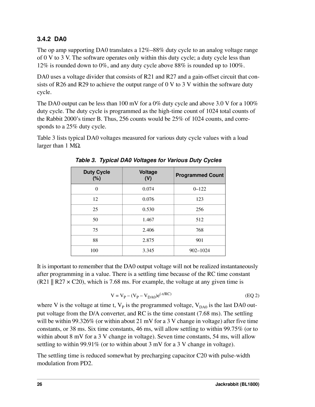
Table 3 lists typical DA0 voltages measured for various duty cycle values with a load larger than 1 MΩ.
Table 3. Typical DA0 Voltages for Various Duty Cycles
Duty Cycle | Voltage | Programmed Count | |
(%) | (V) | ||
| |||
|
|
| |
0 | 0.074 | ||
|
|
| |
12 | 0.076 | 123 | |
|
|
| |
25 | 0.530 | 256 | |
|
|
| |
50 | 1.467 | 512 | |
|
|
| |
75 | 2.406 | 768 | |
|
|
| |
88 | 2.875 | 901 | |
|
|
| |
100 | 3.345 | ||
|
|
|
It is important to remember that the DA0 output voltage will not be realized instantaneously after programming in a value. There is a settling time because of the RC time constant (R21 R27 × C20), which is 7.68 ms. For example, the voltage at any given time is
V = VP – (VP – | (EQ 2) |
where V is the voltage at time t, VP is the programmed voltage, VDA0 is the last DA0 out- put voltage from the D/A converter, and RC is the time constant (7.68 ms). The settling will be within 99.326% (or within about 21 mV for a 3 V change in voltage) after five time constants, or 38 ms. Six time constants, 46 ms, will allow settling to within 99.75% (or to within about 8 mV for a 3 V change in voltage). Seven time constants, 54 ms, will allow settling to within 99.91% (or to within about 3 mV for a 3 V change in voltage).
The settling time is reduced somewhat by precharging capacitor C20 with
26 | Jackrabbit (BL1800) |