B.3.1 Demonstration Board
A relay, a thermistor, four additional LEDs, and a serial cable are included in a bag of parts to further allow exploration of the Jackrabbit‘s operation.
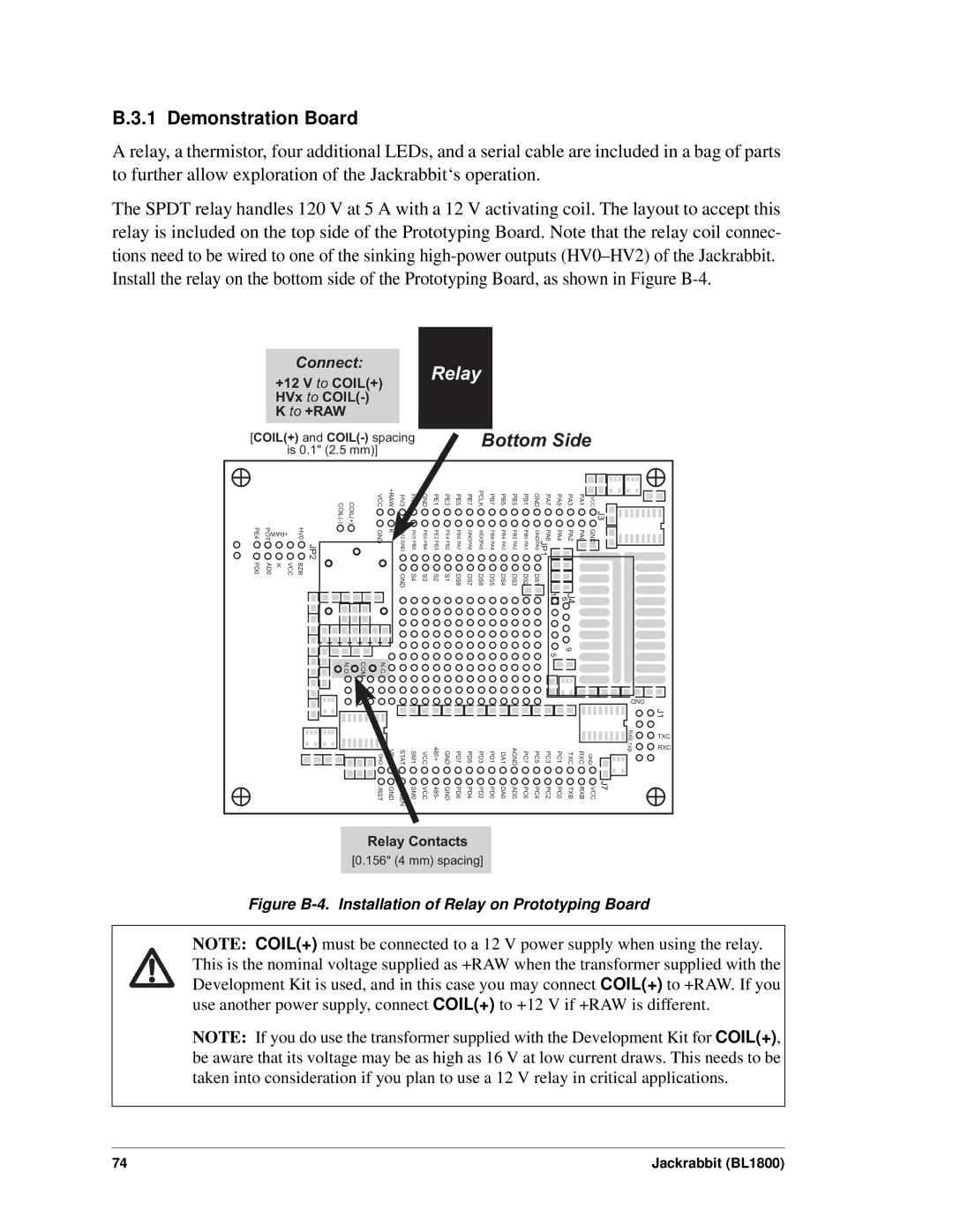
The SPDT relay handles 120 V at 5 A with a 12 V activating coil. The layout to accept this relay is included on the top side of the Prototyping Board. Note that the relay coil connec- tions need to be wired to one of the sinking
|
|
| Connect: |
|
|
|
|
| Relay |
|
|
|
|
|
|
|
|
|
|
|
| ||||
|
| +12 V to COIL(+) |
|
|
|
|
|
|
|
|
|
|
|
|
|
|
|
| |||||||
|
|
|
|
|
|
|
|
|
|
|
|
|
|
|
|
|
|
|
|
|
|
| |||
|
| HVx to |
|
|
|
|
|
|
|
|
|
|
|
|
|
|
|
|
|
|
|
|
|
| |
|
| K to +RAW |
|
|
|
|
|
|
|
|
|
|
|
|
|
|
|
|
|
|
|
|
|
| |
[COIL(+) and |
|
|
|
|
| Bottom Side |
|
| |||||||||||||||||
|
| is 0.1" (2.5 mm)] |
|
|
|
|
|
|
|
|
|
|
|
|
|
|
|
|
|
|
|
|
| ||
|
|
| COIL(+) | VCC | +RAW | HV3 | HV1 | GND | PE1 | PE3 | PE5 | PE7 | PCLK | PB7 | PB5 | PB3 | PB1 | GND | PA7 | PA5 | PA3 | PA1 | VCC | J3 |
|
PE4 | +RAW | JP2 HV0 |
|
|
|
|
|
|
|
|
|
|
|
|
|
|
| PA6 |
|
|
|
|
|
| |
POT |
| GND | K |
|
|
|
|
|
|
|
|
|
|
|
|
| PA4 | PA2 | PA0 | GND |
|
| |||
| GND | PB5HV0 | PE0PB4 | PE2PB3 | PE4PB2 | PA7PE6 | PA6GND | PA5WDO | PA4PB6 | PA3PB4 | PA2PB2 | PA1PB0 | JP1 PA0GND |
|
| ||||||||||
PD0 | AD0 | K | BZR VCC |
|
| GND | S4 | S3 | S2 | S1 | DS8 | DS7 | DS6 | DS5 | DS4 | DS3 | DS2 | DS1 |
|
|
|
|
|
|
|
|
|
|
|
|
|
|
|
|
|
|
|
|
|
|
|
|
|
|
| 6 |
|
|
|
| |
|
|
|
|
|
|
|
|
|
|
|
|
|
|
|
|
|
|
| 1 | J4 |
|
|
|
| |
|
|
|
|
|
|
|
|
|
|
|
|
|
|
|
|
|
|
|
|
| 9 |
|
|
|
|
|
|
|
|
|
|
|
|
|
|
|
|
|
|
|
|
|
|
| 5 |
|
|
|
|
| |
|
|
| COM N.O. | N.C. |
|
|
|
|
|
|
|
|
|
|
|
|
|
|
|
|
|
|
|
|
|
|
|
|
|
|
|
|
|
|
|
|
|
|
|
|
|
|
|
|
|
|
|
|
| GND |
|
|
|
|
|
|
|
|
|
|
|
|
|
|
|
|
|
|
|
|
|
|
|
|
|
| J1 |
|
|
|
|
|
|
|
|
|
|
|
|
|
|
|
|
|
|
|
|
|
|
|
| RXB | TXC |
|
|
|
|
| VBAT | STAT | SM1 | VCC | 485+ | GND | PD7 | PD5 | PD3 | PD1 | DA1 | AGND | PC7 | PC5 | PC3 | PC1 | TXC | RXC |
| TXB | RXC |
|
|
|
| GND | GND |
| |||||||||||||||||||
|
|
|
| /RST | GND | IOBEN | SM0 | VCC | 485- | GND | PD6 | PD4 | PD2 | PD0 | DA0 | AD0 | PC6 | PC4 | PC2 | PC0 | TXB | RXB | VCC | J7 |
|
Relay Contacts
[0.156" (4 mm) spacing]
Figure B-4. Installation of Relay on Prototyping Board
NOTE: COIL(+) must be connected to a 12 V power supply when using the relay. This is the nominal voltage supplied as +RAW when the transformer supplied with the Development Kit is used, and in this case you may connect COIL(+) to +RAW. If you use another power supply, connect COIL(+) to +12 V if +RAW is different.
NOTE: If you do use the transformer supplied with the Development Kit for COIL(+), be aware that its voltage may be as high as 16 V at low current draws. This needs to be taken into consideration if you plan to use a 12 V relay in critical applications.
74 | Jackrabbit (BL1800) |