A.2 Jumper Configurations
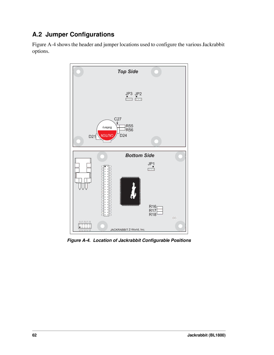
Figure A-4 shows the header and jumper locations used to configure the various Jackrabbit options.
Top Side
JP3 JP2
D21
| C27 | |
Battery | R55 | |
R56 | ||
| ||
CAUTION | D24 |
Bottom Side
JP1
R16
R17 ![]()
R18 ![]()
JACKRABBIT
Figure A-4. Location of Jackrabbit Configurable Positions
62 | Jackrabbit (BL1800) |
