Internal Serial Controller (2500S)
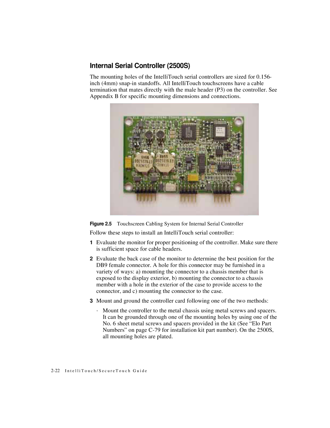
The mounting holes of the IntelliTouch serial controllers are sized for 0.156- inch (4mm)
Figure 2.5 Touchscreen Cabling System for Internal Serial Controller
Follow these steps to install an IntelliTouch serial controller:
1Evaluate the monitor for proper positioning of the controller. Make sure there is sufficient space for cable headers.
2Evaluate the back case of the monitor to determine the best position for the DB9 female connector. A hole for this connector may be furnished in a variety of ways: a) mounting the connector to a chassis member that is exposed to the display exterior, b) mounting the connector to a chassis member with a hole in the exterior of the case to provide access to the connector, and c) mounting the connector to the case.
3Mount and ground the controller card following one of the two methods:
•Mount the controller to the metal chassis using metal screws and spacers. It can be grounded through one of the mounting holes by using one of the No. 6 sheet metal screws and spacers provided in the kit (See “Elo Part Numbers” on page
