Connectors and Pin Definitions
Serial connector, P2, and signal descriptions
Touchscreen connector, P3, and signal descriptions
Power connector, P4
The connector configuration permits the controller to be placed in-line between the touchscreen and serial I/O attachments.
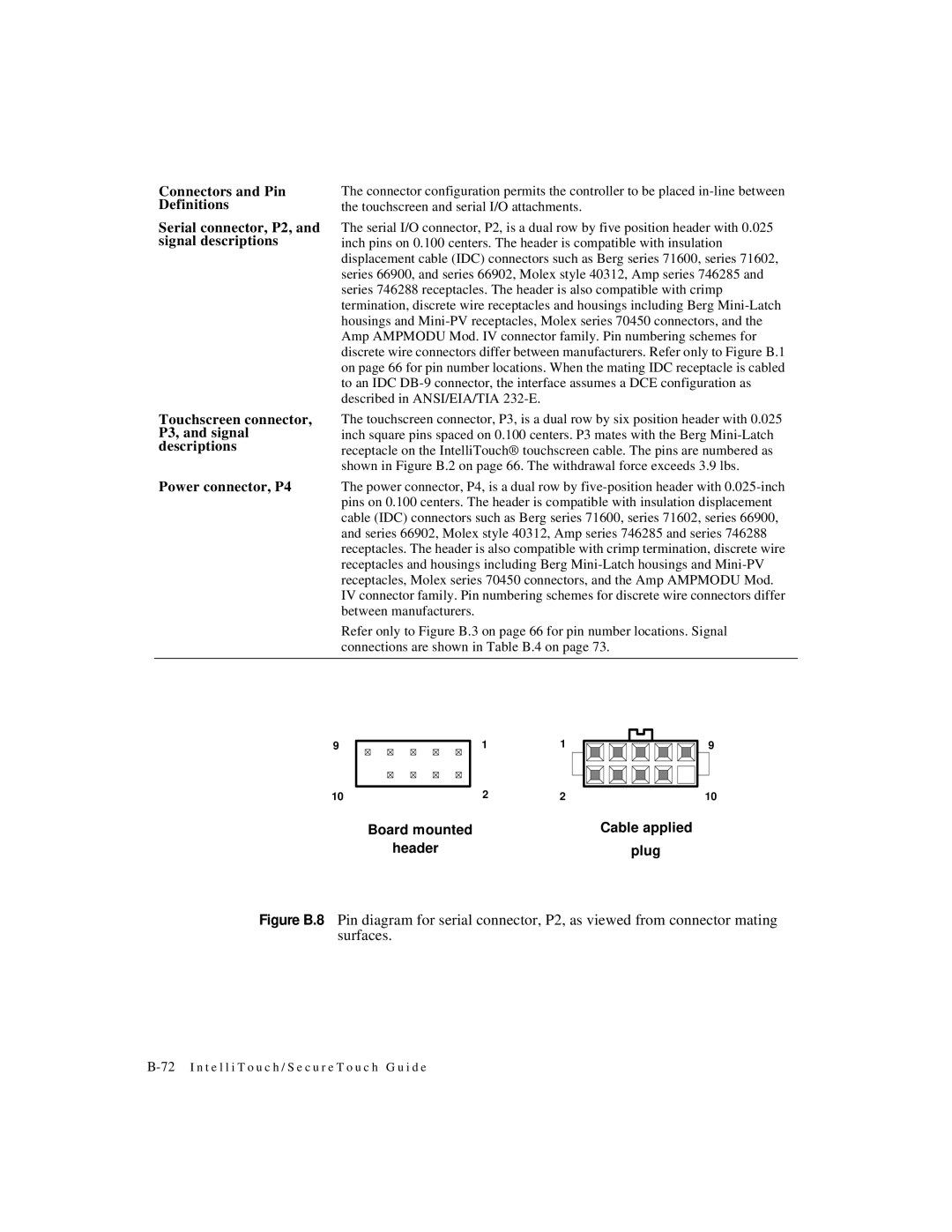
The serial I/O connector, P2, is a dual row by five position header with 0.025 inch pins on 0.100 centers. The header is compatible with insulation displacement cable (IDC) connectors such as Berg series 71600, series 71602, series 66900, and series 66902, Molex style 40312, Amp series 746285 and series 746288 receptacles. The header is also compatible with crimp termination, discrete wire receptacles and housings including Berg Mini-Latch housings and Mini-PV receptacles, Molex series 70450 connectors, and the Amp AMPMODU Mod. IV connector family. Pin numbering schemes for discrete wire connectors differ between manufacturers. Refer only to Figure B.1 on page 66 for pin number locations. When the mating IDC receptacle is cabled to an IDC DB-9 connector, the interface assumes a DCE configuration as described in ANSI/EIA/TIA 232-E.
The touchscreen connector, P3, is a dual row by six position header with 0.025 inch square pins spaced on 0.100 centers. P3 mates with the Berg Mini-Latch receptacle on the IntelliTouch® touchscreen cable. The pins are numbered as shown in Figure B.2 on page 66. The withdrawal force exceeds 3.9 lbs.
The power connector, P4, is a dual row by five-position header with 0.025-inch pins on 0.100 centers. The header is compatible with insulation displacement cable (IDC) connectors such as Berg series 71600, series 71602, series 66900, and series 66902, Molex style 40312, Amp series 746285 and series 746288 receptacles. The header is also compatible with crimp termination, discrete wire receptacles and housings including Berg Mini-Latch housings and Mini-PV receptacles, Molex series 70450 connectors, and the Amp AMPMODU Mod. IV connector family. Pin numbering schemes for discrete wire connectors differ between manufacturers.
Refer only to Figure B.3 on page 66 for pin number locations. Signal connections are shown in Table B.4 on page 73.

