RS-232 Connections
Review cable connections and switch settings. If you have used your own cables or adapters for connection to the serial port, check pinouts. Verify that the data transfer rate (baud rate) of the computer's serial port is the same as selected by switches or jumpers on the controller.
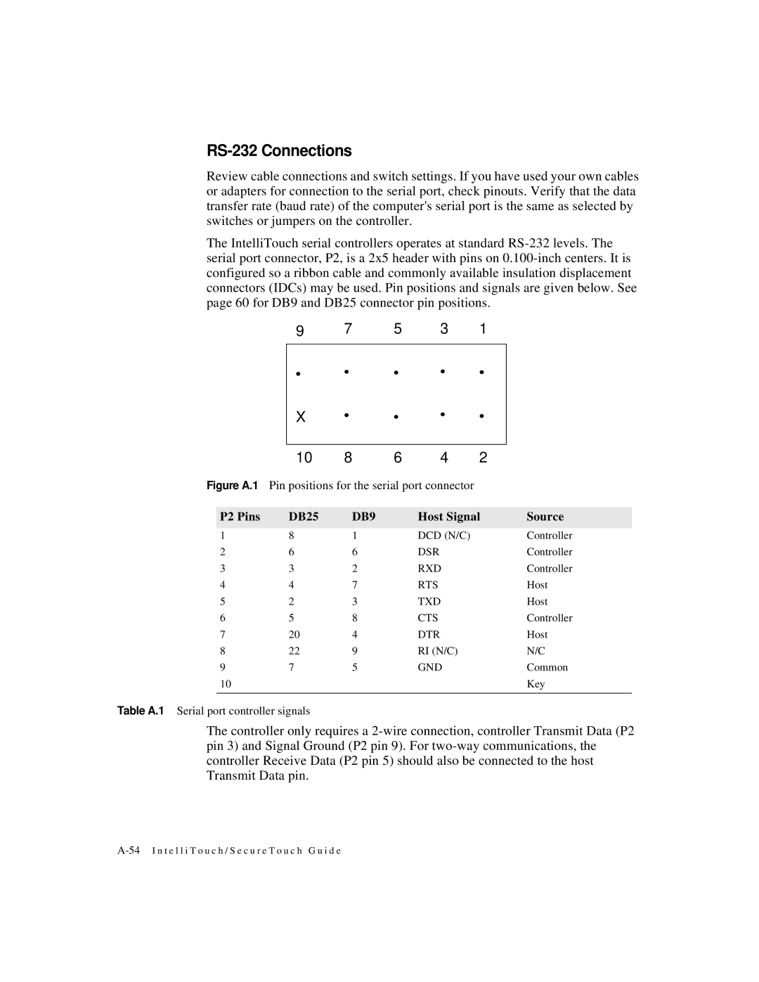
The IntelliTouch serial controllers operates at standard
9 | 7 | 5 | 3 | 1 |
|
| X |
|
|
|
|
|
|
|
|
|
|
|
|
|
|
| 10 | 8 | 6 | 4 | 2 |
|
Figure A.1 Pin positions for the serial port connector |
|
| |||||
|
|
|
|
|
|
| |
| P2 Pins | DB25 | DB9 |
| Host Signal | Source | |
|
|
|
|
|
|
|
|
1 | 8 | 1 |
| DCD (N/C) |
| Controller | |
2 | 6 | 6 |
| DSR |
| Controller | |
3 | 3 | 2 |
| RXD |
| Controller | |
4 | 4 | 7 |
| RTS |
| Host | |
5 | 2 | 3 |
| TXD |
| Host | |
6 | 5 | 8 |
| CTS |
| Controller | |
7 | 20 | 4 |
| DTR |
| Host | |
8 | 22 | 9 |
| RI (N/C) |
| N/C | |
9 | 7 | 5 |
| GND |
| Common | |
10 |
|
|
|
|
| Key | |
|
|
|
|
|
|
|
|
Table A.1 Serial port controller signals
The controller only requires a