2 | 12 | 12 |
1 | 11 | 11 |
|
|
2
1
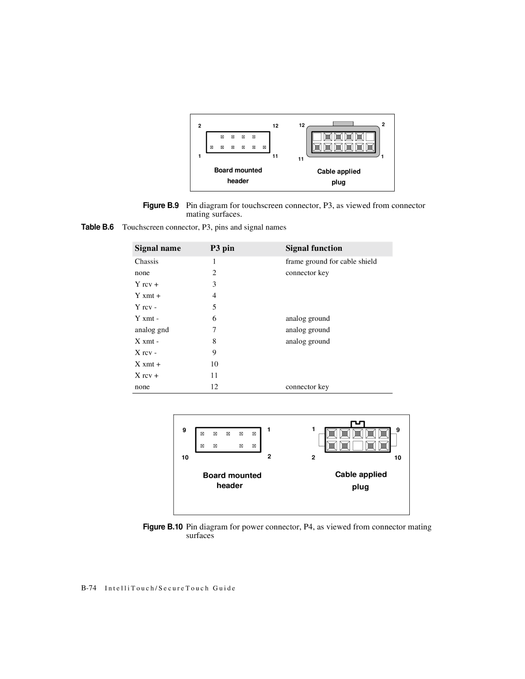
Board mounted | Cable applied |
header | plug |
Figure B.9 Pin diagram for touchscreen connector, P3, as viewed from connector mating surfaces.
Table B.6 Touchscreen connector, P3, pins and signal names
Signal name | P3 pin | Signal function |
|
|
|
Chassis | 1 | frame ground for cable shield |
none | 2 | connector key |
Y rcv + | 3 |
|
Y xmt + | 4 |
|
Y rcv - | 5 |
|
Y xmt - | 6 | analog ground |
analog gnd | 7 | analog ground |
X xmt - | 8 | analog ground |
X rcv - | 9 |
|
X xmt + | 10 |
|
X rcv + | 11 |
|
none | 12 | connector key |
|
|
|
9
10
1 | 1 | 9 |
2 | 2 | 10 |
Board mounted | Cable applied |
header | plug |