12.3MOTOR ASSEMBLY & DISASSEMBLY
1.Remove the rotor by using a 16mm or 5/8" socket. Lift the rotor clear, and place in a plastic bag. The rotor has strong magnets and can attract metal objects. If any foreign objects are caught in the rotor area these may cause the magnets to wear and create a fine black powder which will permeate through the whole appliance.
2.Unscrew the 4 bolts securing the stator to the outer bowl using a 3/8" socket.
3.Lift the stator clear of the shaft, turn over.
NB: When placing the stator on a work bench, ensure the
RPS connectors are facing upwards or damage can result. Do not place the stator inside the rotor.
ASSEMBLY
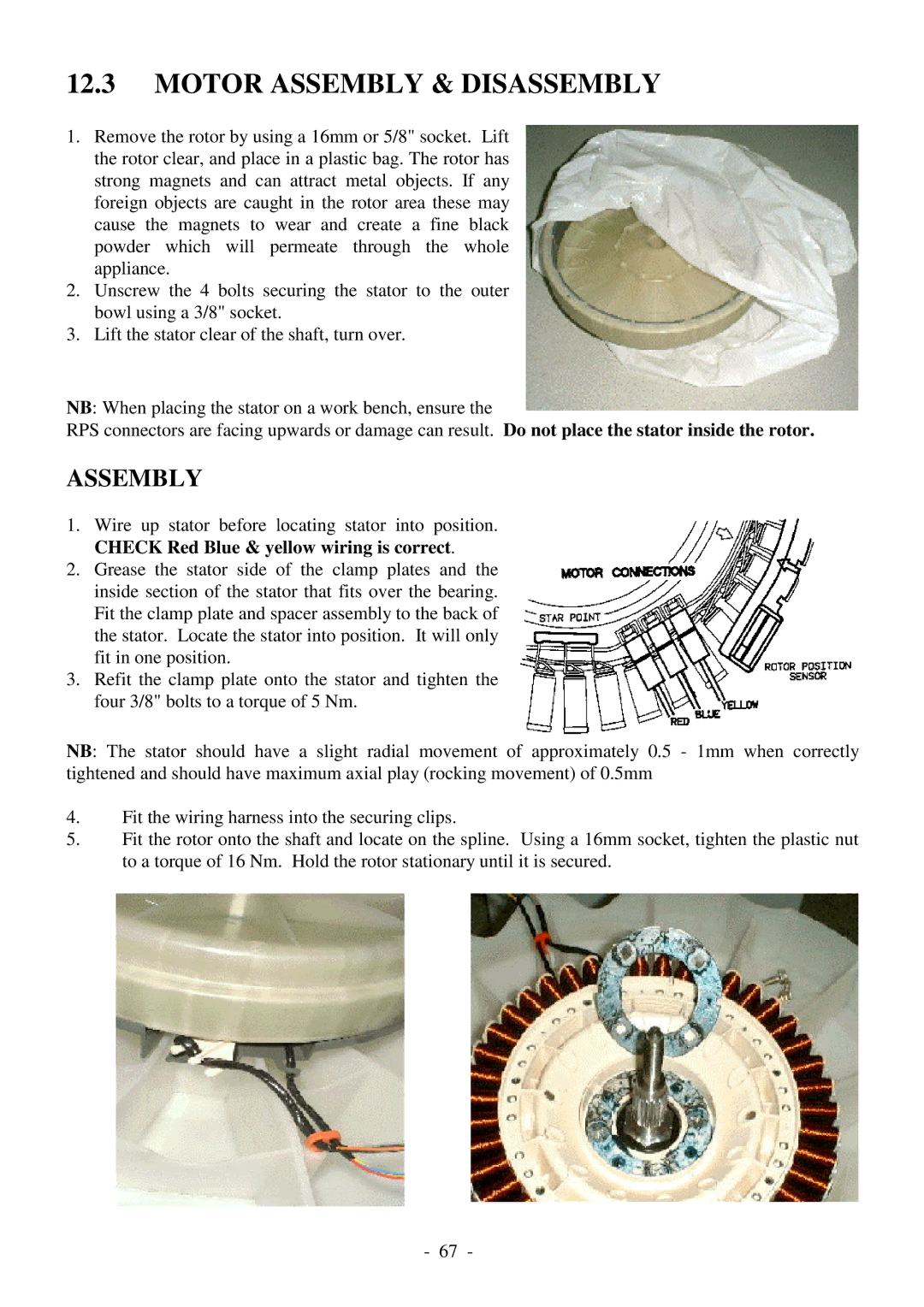
1.Wire up stator before locating stator into position. CHECK Red Blue & yellow wiring is correct.
2.Grease the stator side of the clamp plates and the inside section of the stator that fits over the bearing. Fit the clamp plate and spacer assembly to the back of the stator. Locate the stator into position. It will only fit in one position.
3.Refit the clamp plate onto the stator and tighten the four 3/8" bolts to a torque of 5 Nm.
NB: The stator should have a slight radial movement of approximately 0.5 - 1mm when correctly tightened and should have maximum axial play (rocking movement) of 0.5mm
4.Fit the wiring harness into the securing clips.
5.Fit the rotor onto the shaft and locate on the spline. Using a 16mm socket, tighten the plastic nut to a torque of 16 Nm. Hold the rotor stationary until it is secured.
- 67 -