WM51 DIAGNOSTIC FLOW CHART – Sept 1992– Phase 1 only
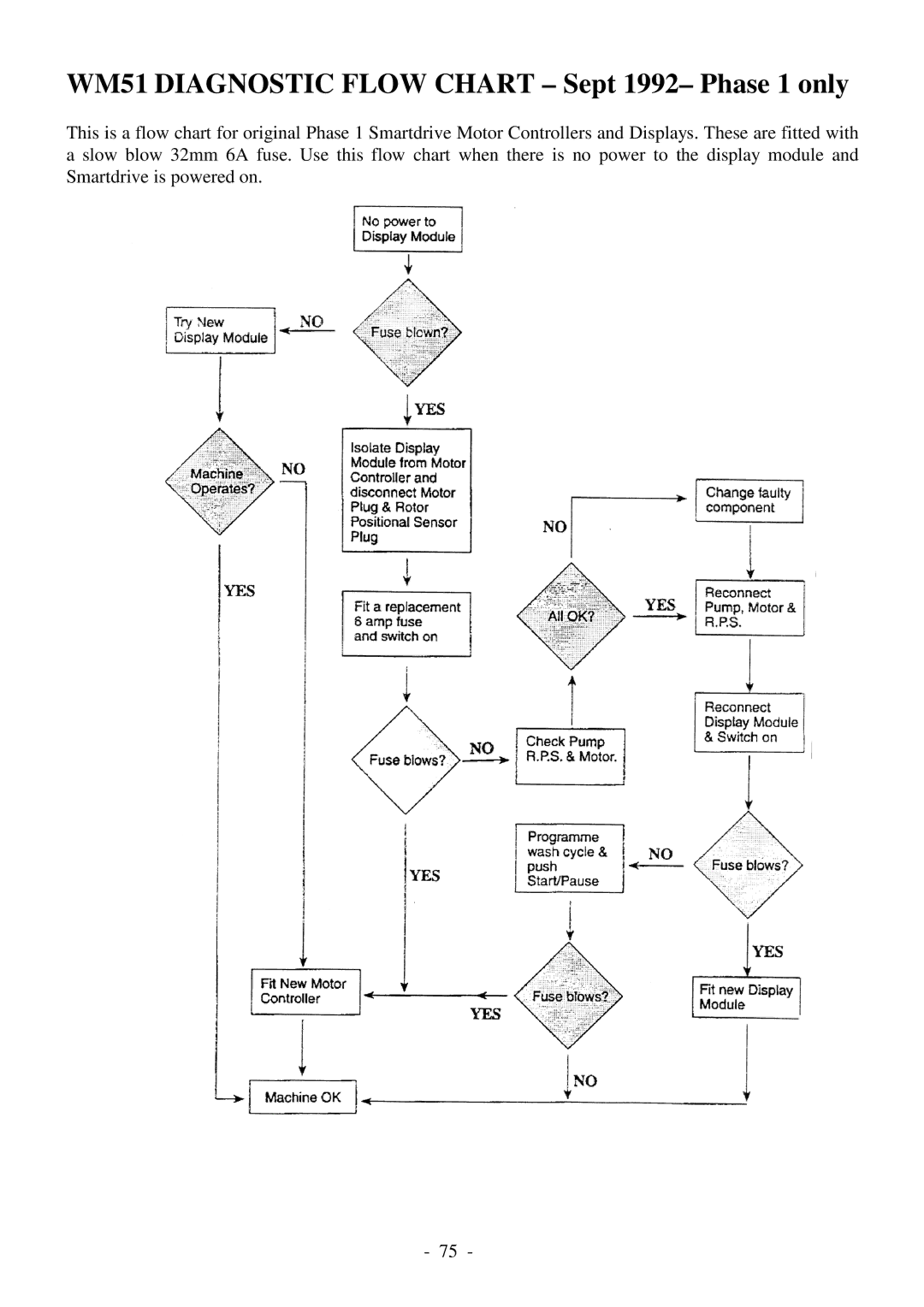
This is a flow chart for original Phase 1 Smartdrive Motor Controllers and Displays. These are fitted with a slow blow 32mm 6A fuse. Use this flow chart when there is no power to the display module and Smartdrive is powered on.
- 75 -