Security Features
In tunnel mode, at each IKE end point, the IP traffic to be protected is completely encapsulated with another IP packet. In this, the inner IP header remains the same as seen in the original traffic to be protected. In the outer IP header, the source and destination addresses are the addresses of the tunnel end points.
Typically, for a remote user, the source address of the outer IP header is the dynamic public IP address provided by the ISP. When mode configuration is enabled, the source address of the inner IP header is the private address allocated by the VPN server to the VPN client.
As in the case of user group method, the administrator creates an IKE policy for a logical group of users such as a department in an organization. The identity information used to identify each user uniquely is configured in the IKE policy. The IKE policy is attached to a mode configuration record. The mode configuration record contains an IPSec policy template to be used for creating dynamic IPSec policy. Also, the record contains one or more pools of private IP addresses to be used for allocating the addresses to the VPN clients. Besides the private IP address, the VPN server can also provide WINS and DNS server addresses.
Upon successful IKE authentication of a VPN client, the server checks whether the IKE policy used to authenticate the VPN client is enabled for mode configuration. If so, the server allocates a private IP address from one of the IP pools in the mode configuration record to the VPN client. The destination address field in the IPSec template attached to the user group is filled in with the private IP address allocated to the VPN client and this is installed as an IPSec policy.
Example 1: Securely Managing the Foundry AR1204 Over an IPSec Tunnel
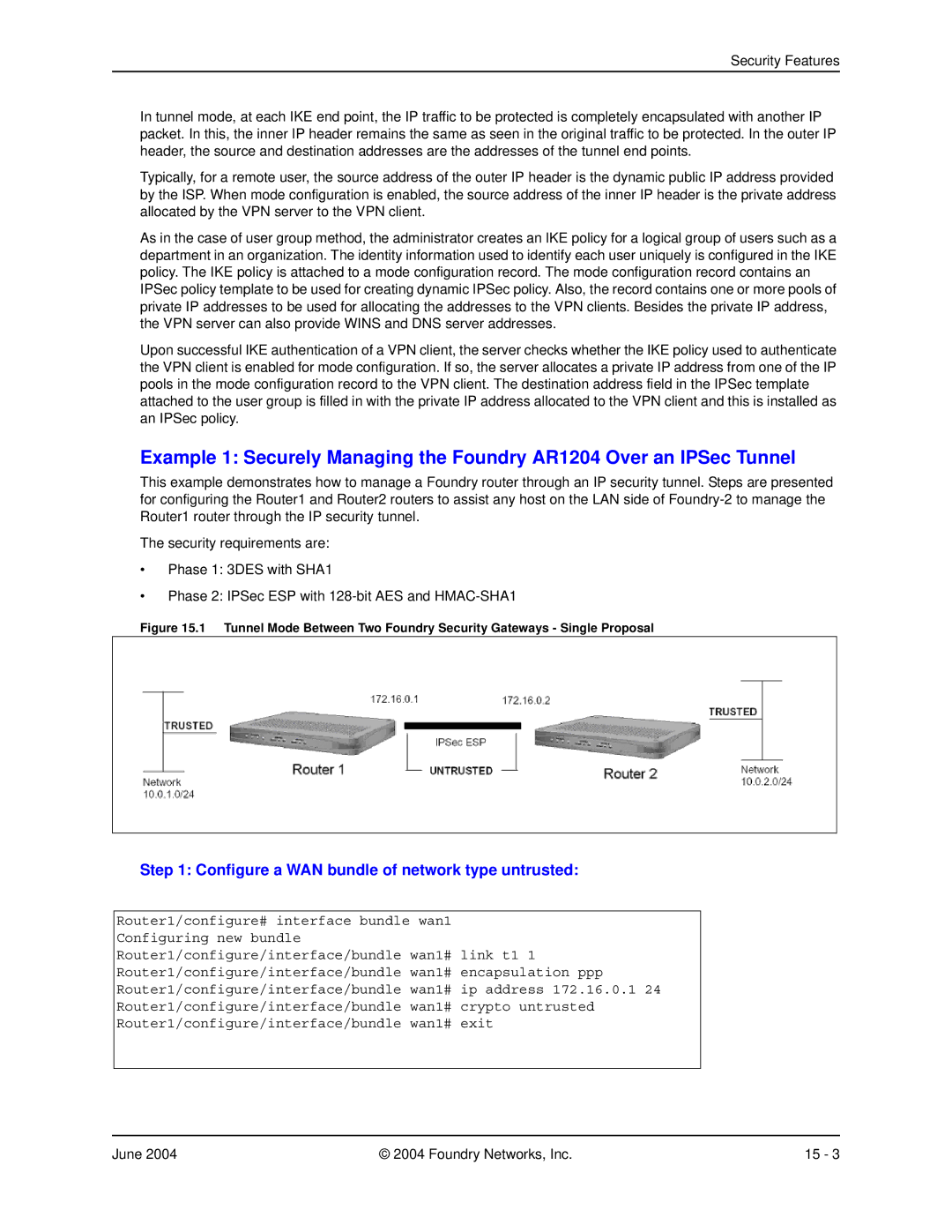
This example demonstrates how to manage a Foundry router through an IP security tunnel. Steps are presented for configuring the Router1 and Router2 routers to assist any host on the LAN side of
The security requirements are:
•Phase 1: 3DES with SHA1
•Phase 2: IPSec ESP with
Figure 15.1 Tunnel Mode Between Two Foundry Security Gateways - Single Proposal
Step 1: Configure a WAN bundle of network type untrusted:
Router1/configure# interface bundle wan1 Configuring new bundle Router1/configure/interface/bundle wan1# link t1 1 Router1/configure/interface/bundle wan1# encapsulation ppp Router1/configure/interface/bundle wan1# ip address 172.16.0.1 24 Router1/configure/interface/bundle wan1# crypto untrusted Router1/configure/interface/bundle wan1# exit
June 2004 | © 2004 Foundry Networks, Inc. | 15 - 3 |