Security Features
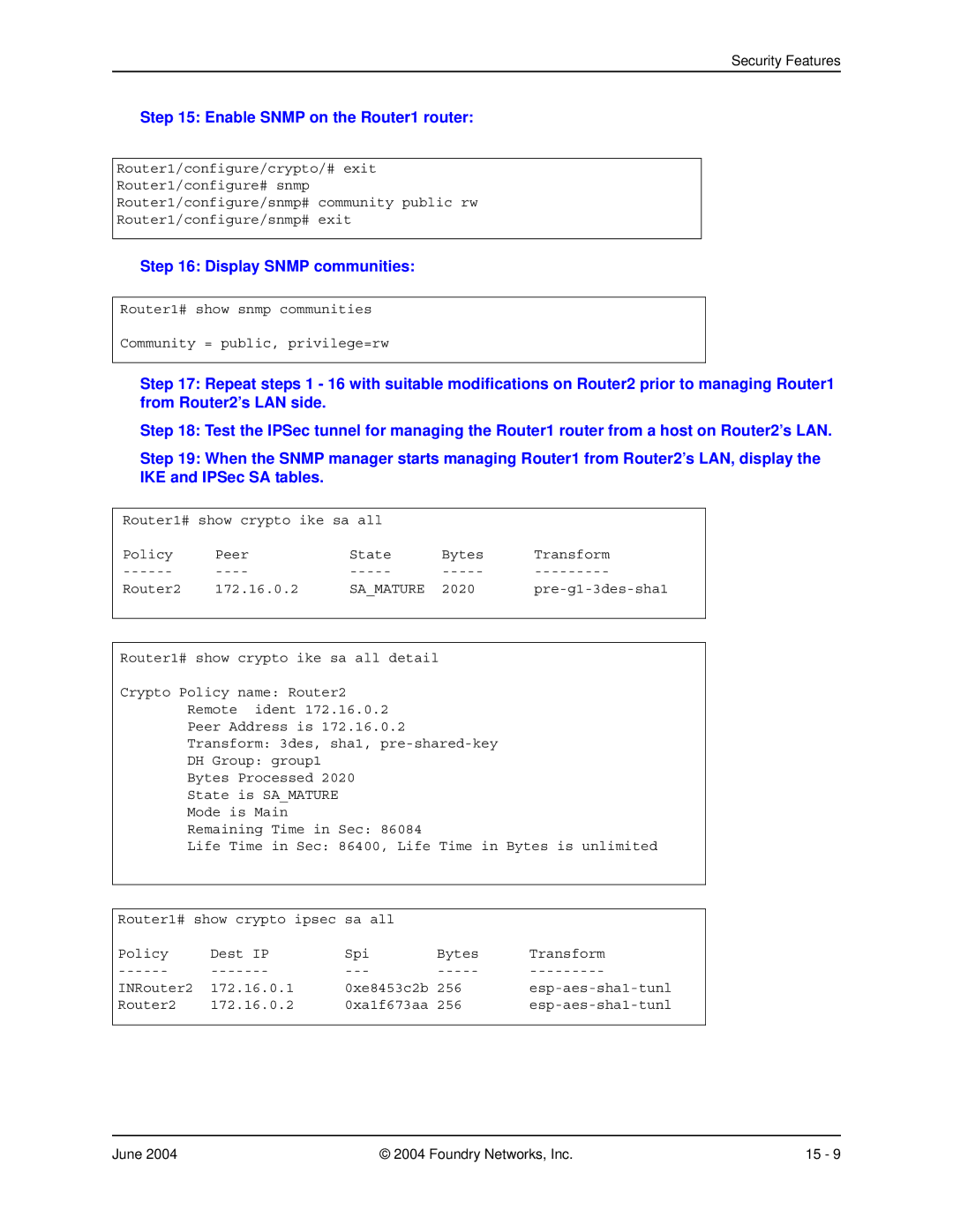
Step 15: Enable SNMP on the Router1 router:
Router1/configure/crypto/# exit
Router1/configure# snmp
Router1/configure/snmp# community public rw
Router1/configure/snmp# exit
Step 16: Display SNMP communities:
Router1# show snmp communities
Community = public, privilege=rw
Step 17: Repeat steps 1 - 16 with suitable modifications on Router2 prior to managing Router1 from Router2’s LAN side.
Step 18: Test the IPSec tunnel for managing the Router1 router from a host on Router2’s LAN.
Step 19: When the SNMP manager starts managing Router1 from Router2’s LAN, display the IKE and IPSec SA tables.
Router1# show crypto ike sa all |
|
| ||
Policy | Peer | State | Bytes | Transform |
Router2 | 172.16.0.2 | SA_MATURE | 2020 | |
|
|
|
|
|
Router1# show crypto ike sa all detail
Crypto Policy name: Router2
Remote ident 172.16.0.2
Peer Address is 172.16.0.2
Transform: 3des, sha1,
DH Group: group1
Bytes Processed 2020
State is SA_MATURE
Mode is Main
Remaining Time in Sec: 86084
Life Time in Sec: 86400, Life Time in Bytes is unlimited
Router1# show crypto ipsec sa all |
|
| ||
Policy | Dest IP | Spi | Bytes | Transform |
INRouter2 | 172.16.0.1 | 0xe8453c2b | 256 | |
Router2 | 172.16.0.2 | 0xa1f673aa | 256 | |
|
|
|
|
|
June 2004 | © 2004 Foundry Networks, Inc. | 15 - 9 |