Connections
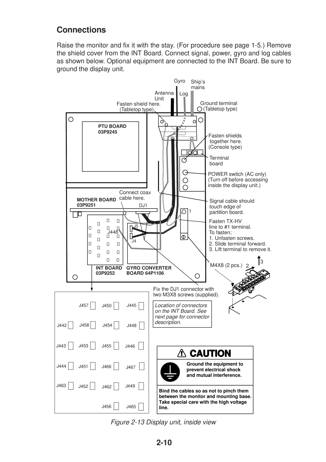
Raise the monitor and fix it with the stay. (For procedure see page
|
| Gyro Ship’s | |
| Antenna | mains | |
| Log |
| |
| Unit |
| Ground terminal |
| Fasten shield here. |
| |
| (Tabletop type) |
| (Tabletop type) |
| PTU BOARD |
|
|
| 03P9245 |
| Fasten shields |
|
|
| |
|
|
| together here. |
|
|
| (Console type) |
|
|
| Terminal |
|
|
| board |
|
|
| POWER switch (AC only) |
|
|
| (Turn off before accessing |
|
|
| inside the display unit.) |
| Connect coax |
|
|
MOTHER BOARD cable here. |
| Signal cable should | |
03P9251 | DJ1 | 1 | touch edge of |
|
| partition board. | |
| J5 |
| Fasten |
|
| line to #1 terminal. | |
| J448 |
| To fasten; |
| J4 |
| 1. Unfasten screws. |
|
| 2. Slide terminal forward. | |
|
|
| |
|
|
| 3. Lift terminal to remove it. |
|
| M4X8 (2 pcs.) | 3 |
INT BOARD | GYRO CONVERTER | 2 | |
|
| ||
03P9252 | BOARD 64P1106 |
| 1 |
|
|
| 2 |
|
|
| 3 |
![]()
![]() 5
5 ![]()
![]() 6
6
![]() 4
4
Fix the DJ1 connector with two M3X8 screws (supplied).
![]()
![]() 7
7 ![]() 8
8
J442 ![]()
![]()
J443
J444
J463
J457 |
| J450 |
| J445 | |
|
|
|
|
|
|
J458 |
| J454 |
| J448 | |
|
| ||||
J453 |
|
|
|
| |
|
|
|
| ||
| J455 |
| J446 | ||
J451 |
|
|
|
| |
| J466 |
| J467 | ||
J452 |
|
|
|
| J449 |
|
| J462 |
| ||
|
|
|
|
|
|
|
|
| J456 |
| J465 |
Location of connectors on the INT Board. See next page for connector description.
![]() CAUTION
CAUTION
Ground the equipment to prevent electrical shock and mutual interference.
Bind the cables so as not to pinch them between the monitor and mounting base. Take special care with the high voltage line.