4.7 Connection of Rate-of-Turn Signal
Connection
1.Connect cable
2.Raise the monitor and fix it with the stay. See page
3.Remove the INT board shield cover by loosening four screws.
4.Connect the
Checking operation
1.Turn on both the ROT device and the radar. Confirm that both the radar and the ROT device are showing the same ROT indication.
2.If the indications are the same close the INT board shield cover and monitor. If the indications are different do the following:
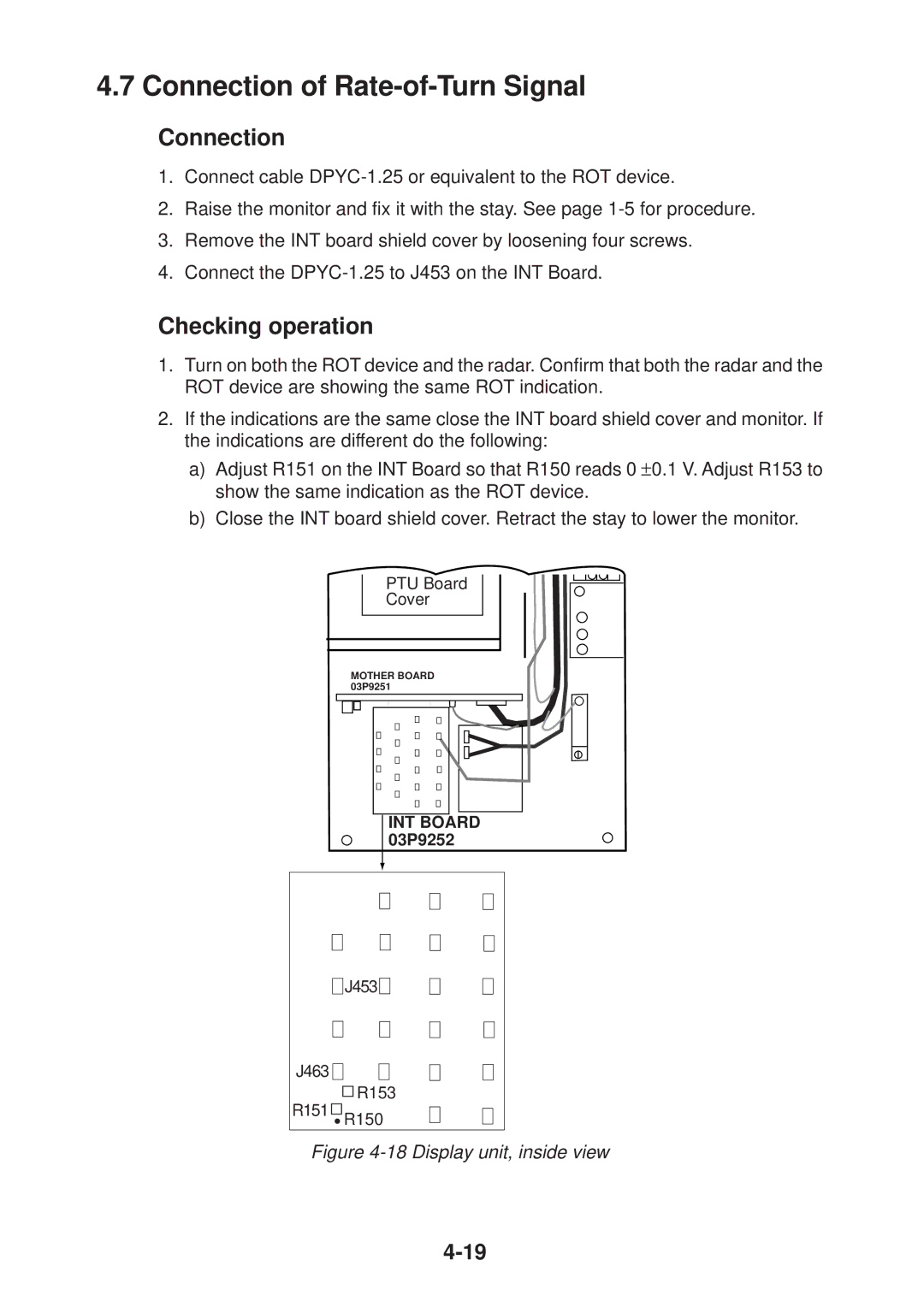
a)Adjust R151 on the INT Board so that R150 reads 0 ±0.1 V. Adjust R153 to show the same indication as the ROT device.
b)Close the INT board shield cover. Retract the stay to lower the monitor.
PTU Board
Cover
MOTHER BOARD 03P9251
INT BOARD 03P9252
![]()
![]() J453
J453![]()
![]()
J463 ![]()
![]()
![]()
![]() R153
R153
R151 ![]()
![]()
![]() R150
R150