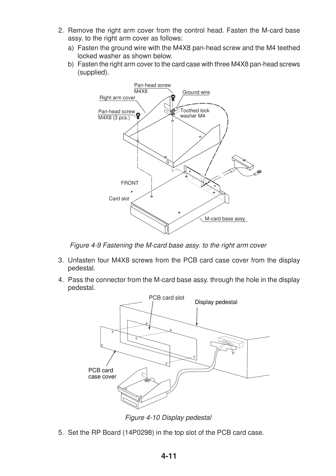
2.Remove the right arm cover from the control head. Fasten the
a)Fasten the ground wire with the M4X8
b)Fasten the right arm cover to the card case with three M4X8
| |
M4X8 | Ground wire |
Right arm cover |
|
Toothed lock | |
M4X8 (3 pcs.) | washer M4 |
|
FRONT
Card slot
Figure 4-9 Fastening the M-card base assy. to the right arm cover
3.Unfasten four M4X8 screws from the PCB card case cover from the display pedestal.
4.Pass the connector from the
PCB card slot
Display pedestal
PCB card case cover
Figure 4-10 Display pedestal
5. Set the RP Board (14P0298) in the top slot of the PCB card case.