Fabricating signal cable S03-75
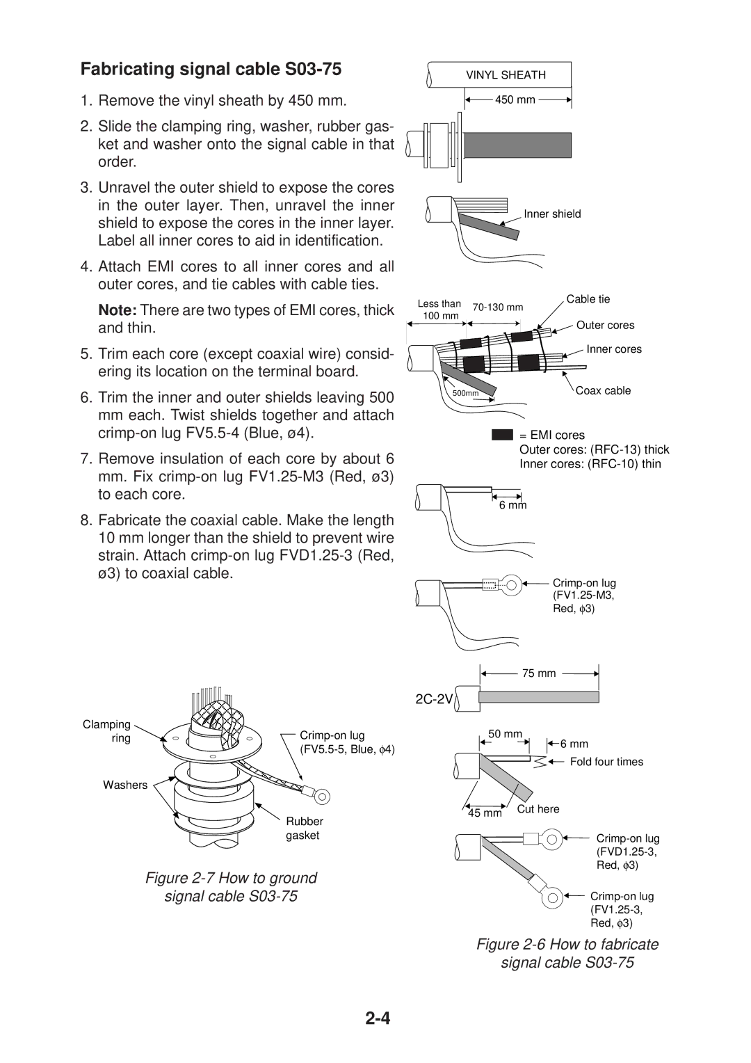
1.Remove the vinyl sheath by 450 mm.
2.Slide the clamping ring, washer, rubber gas- ket and washer onto the signal cable in that order.
3.Unravel the outer shield to expose the cores in the outer layer. Then, unravel the inner shield to expose the cores in the inner layer. Label all inner cores to aid in identification.
4.Attach EMI cores to all inner cores and all outer cores, and tie cables with cable ties.
Note: There are two types of EMI cores, thick and thin.
5.Trim each core (except coaxial wire) consid- ering its location on the terminal board.
6.Trim the inner and outer shields leaving 500
mmeach. Twist shields together and attach
7.Remove insulation of each core by about 6
mm.Fix
8.Fabricate the coaxial cable. Make the length 10 mm longer than the shield to prevent wire strain. Attach
VINYL SHEATH ![]()
![]() 450 mm
450 mm ![]()
![]()
Inner shield
Less than | Cable tie | |
100 mm | ||
|
![]() Outer cores
Outer cores
Inner cores
500mm | Coax cable |
= EMI cores
Outer cores:
Inner cores:
6 mm
![]()
75 mm ![]()
![]()
2C-2V
Clamping ring
Washers
Rubber gasket
50 mm
![]() 6 mm
6 mm
Fold four times
45 mm![]() Cut here
Cut here