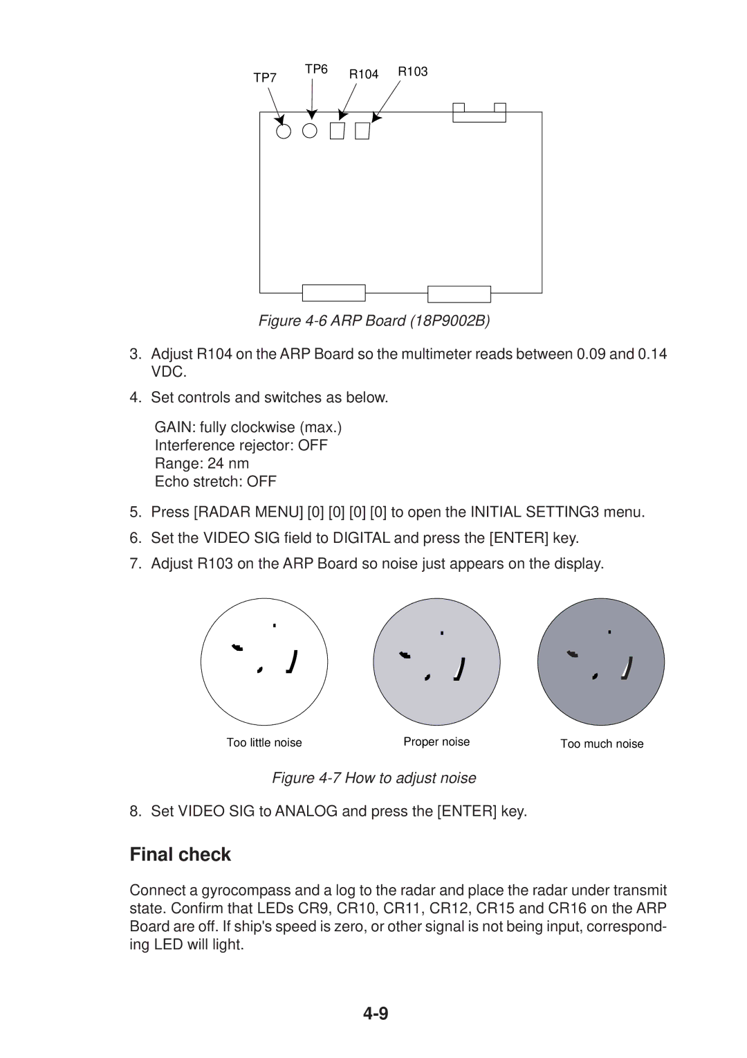
TP6 | R104 | R103 |
TP7 |
|
|
Figure | ||
3.Adjust R104 on the ARP Board so the multimeter reads between 0.09 and 0.14 VDC.
4.Set controls and switches as below.
GAIN: fully clockwise (max.)
Interference rejector: OFF
Range: 24 nm
Echo stretch: OFF
5.Press [RADAR MENU] [0] [0] [0] [0] to open the INITIAL SETTING3 menu.
6.Set the VIDEO SIG field to DIGITAL and press the [ENTER] key.
7.Adjust R103 on the ARP Board so noise just appears on the display.
Too little noise | Proper noise | Too much noise |
Figure 4-7 How to adjust noise
8. Set VIDEO SIG to ANALOG and press the [ENTER] key.
Final check
Connect a gyrocompass and a log to the radar and place the radar under transmit state. Confirm that LEDs CR9, CR10, CR11, CR12, CR15 and CR16 on the ARP Board are off. If ship's speed is zero, or other signal is not being input, correspond- ing LED will light.