7.Attach instruction label (supplied) to shield cover for the INT and GYRO CON- VERTER boards.
8.Close the monitor.
9.Turn the power off and on again to reset the CPU.
Connection of external power supply
An external power supply is necessary when the repeater signal is
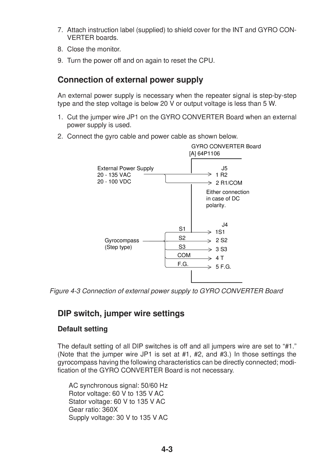
1.Cut the jumper wire JP1 on the GYRO CONVERTER Board when an external power supply is used.
2.Connect the gyro cable and power cable as shown below.
External Power Supply 20 - 135 VAC
20 - 100 VDC
Gyrocompass (Step type)
GYRO CONVERTER Board [A] 64P1106
J5
1R2
2R1/COM
Either connection in case of DC polarity.
S1 | J4 | |
1S1 | ||
S2 | ||
2 S2 | ||
| ||
S3 | 3 S3 | |
COM | ||
4 T | ||
F.G. | ||
5 F.G. | ||
|
Figure 4-3 Connection of external power supply to GYRO CONVERTER Board
DIP switch, jumper wire settings
Default setting
The default setting of all DIP switches is off and all jumpers wire are set to “#1.” (Note that the jumper wire JP1 is set at #1, #2, and #3.) In those settings the gyrocompass having the following characteristics can be directly connected; modi- fication of the GYRO CONVERTER Board is not necessary.
AC synchronous signal: 50/60 Hz
Rotor voltage: 60 V to 135 V AC
Stator voltage: 60 V to 135 V AC
Gear ratio: 360X
Supply voltage: 30 V to 135 V AC