6.Unfasten four M4X8 screws to remove the PCB card case cover at the front of the display pedestal.
7.Set the RP Board (14P0298) in the top slot of the PCB card case.
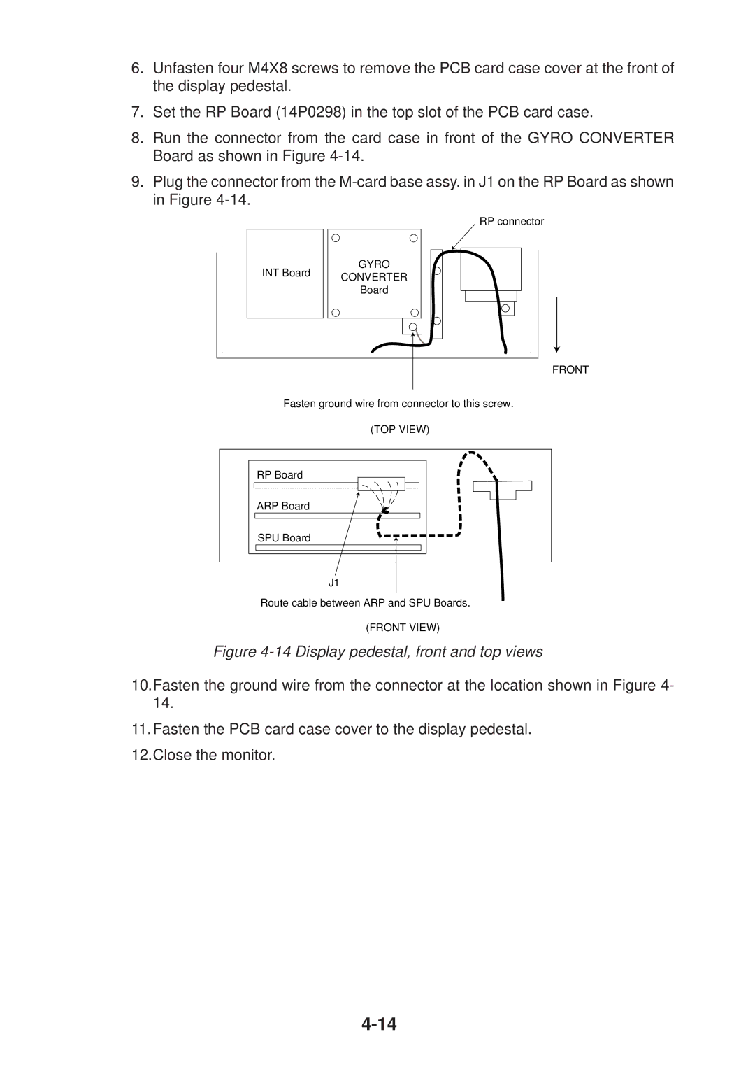
8.Run the connector from the card case in front of the GYRO CONVERTER Board as shown in Figure
9.Plug the connector from the
RP connector
INT Board | GYRO | |
CONVERTER | ||
| ||
| Board |
FRONT
Fasten ground wire from connector to this screw.
(TOP VIEW)
RP Board
ARP Board
SPU Board
J1
Route cable between ARP and SPU Boards.
(FRONT VIEW)
Figure 4-14 Display pedestal, front and top views
10.Fasten the ground wire from the connector at the location shown in Figure 4- 14.
11.Fasten the PCB card case cover to the display pedestal. 12.Close the monitor.