6.Run the connector from the
7.Plug the connector from the
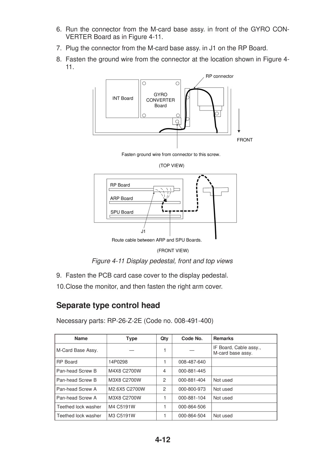
8.Fasten the ground wire from the connector at the location shown in Figure 4- 11.
RP connector
INT Board | GYRO | |
CONVERTER | ||
| ||
| Board |
FRONT
Fasten ground wire from connector to this screw.
(TOP VIEW)
RP Board
ARP Board
SPU Board
J1
Route cable between ARP and SPU Boards.
(FRONT VIEW)
Figure 4-11 Display pedestal, front and top views
9. Fasten the PCB card case cover to the display pedestal. 10.Close the monitor, and then fasten the right arm cover.
Separate type control head
Necessary parts: RP-26-Z-2E (Code no. 008-491-400)
Name | Type | Qty | Code No. | Remarks | |
|
|
|
|
| |
— | 1 | — | IF Board, Cable assy., | ||
|
|
|
| ||
|
|
|
|
| |
RP Board | 14P0298 | 1 |
| ||
|
|
|
|
| |
M4X8 C2700W | 4 |
| |||
|
|
|
|
| |
M3X8 C2700W | 2 | Not used | |||
|
|
|
|
| |
M2.6X5 C2700W | 2 | Not used | |||
|
|
|
|
| |
M3X8 C2700W | 1 | Not used | |||
|
|
|
|
| |
Teethed lock washer | M4 C5191W | 1 |
| ||
|
|
|
|
| |
Teethed lock washer | M3 C5191W | 1 | Not used | ||
|
|
|
|
|