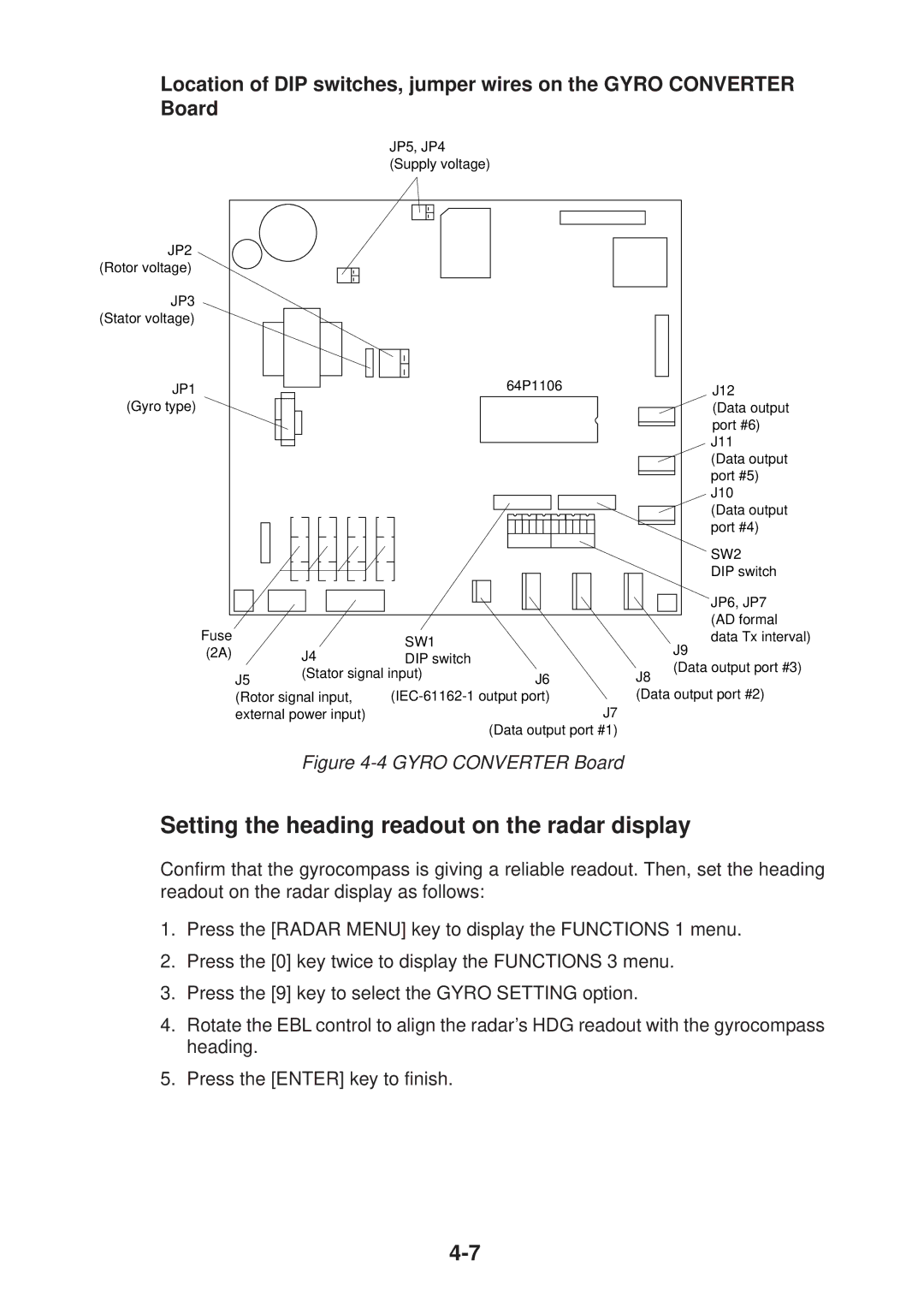
Location of DIP switches, jumper wires on the GYRO CONVERTER Board
JP5, JP4 (Supply voltage)
JP2 (Rotor voltage)
JP3 (Stator voltage)
JP1 |
|
|
|
|
|
|
|
|
|
|
|
|
|
|
|
|
|
| 64P1106 | J12 | |||||
|
|
|
|
|
|
|
|
|
|
|
|
|
|
|
|
|
| ||||||||
(Gyro type) |
|
|
|
|
|
|
|
|
|
|
|
|
|
|
|
|
|
|
|
| (Data output | ||||
|
|
|
|
|
|
|
|
|
|
|
|
|
|
|
|
|
|
|
|
|
|
|
|
| port #6) |
|
|
|
|
|
|
|
|
|
|
|
|
|
|
|
|
|
|
|
|
|
|
|
|
| J11 |
|
|
|
|
|
|
|
|
|
|
|
|
|
|
|
|
|
|
|
|
|
|
|
|
| |
|
|
|
|
|
|
|
|
|
|
|
|
|
|
|
|
|
|
|
|
|
|
|
|
| |
|
|
|
|
|
|
|
|
|
|
|
|
|
|
|
|
|
|
|
|
|
|
|
|
| (Data output |
|
|
|
|
|
|
|
|
|
|
|
|
|
|
|
|
|
|
|
|
|
|
|
|
| port #5) |
|
|
|
|
|
|
|
|
|
|
|
|
|
|
|
|
|
|
|
|
|
|
|
|
| J10 |
|
|
|
|
|
|
|
|
|
|
|
|
|
|
|
|
|
|
|
|
|
|
|
|
| (Data output |
|
|
|
|
|
|
|
|
|
|
|
|
|
|
|
|
|
|
|
|
|
|
|
|
| port #4) |
|
|
|
|
|
|
|
|
|
|
|
|
|
|
|
|
|
|
|
|
|
|
|
|
| SW2 |
|
|
|
|
|
|
|
|
|
|
|
|
|
|
|
|
|
|
|
|
|
|
|
|
| |
|
|
|
|
|
|
|
|
|
|
|
|
|
|
|
|
|
|
|
|
|
|
|
|
| DIP switch |
|
|
|
|
|
|
|
|
|
|
|
|
|
|
|
|
|
|
|
|
|
|
|
|
| JP6, JP7 |
|
|
|
|
|
|
|
|
|
|
|
|
|
|
|
|
|
|
|
|
|
|
|
|
| |
Fuse |
|
|
|
|
|
|
|
|
|
|
|
|
|
|
|
|
|
|
| (AD formal | |||||
|
|
|
|
|
|
|
|
|
|
|
|
|
|
|
|
| SW1 |
| data Tx interval) | ||||||
(2A) |
|
|
|
| J4 |
|
|
|
|
| J9 | ||||||||||||||
|
|
|
|
|
|
|
| DIP switch |
| ||||||||||||||||
|
|
|
|
|
|
|
|
| (Data output port #3) | ||||||||||||||||
|
|
|
|
|
|
|
|
|
| (Stator signal input) |
| ||||||||||||||
| J5 |
|
|
|
| J6 | J8 | ||||||||||||||||||
| (Rotor signal input, |
|
|
| (Data output port #2) | ||||||||||||||||||||
| external power input) |
|
|
|
|
|
| J7 | |||||||||||||||||
|
|
|
|
|
|
|
|
|
|
|
|
|
|
|
|
|
|
|
|
|
|
|
| (Data output port #1) | |
Figure 4-4 GYRO CONVERTER Board
Setting the heading readout on the radar display
Confirm that the gyrocompass is giving a reliable readout. Then, set the heading readout on the radar display as follows:
1.Press the [RADAR MENU] key to display the FUNCTIONS 1 menu.
2.Press the [0] key twice to display the FUNCTIONS 3 menu.
3.Press the [9] key to select the GYRO SETTING option.
4.Rotate the EBL control to align the radar’s HDG readout with the gyrocompass heading.
5.Press the [ENTER] key to finish.