INSTALLATION OF OPTIONAL EQUIPMENT
4.1 Gyro Converter GC-8
The Gyro Converter
This section explains how to install and the
Installation and connection of the GYRO
CONVERTER Board
Necessary Parts: GC-8 (Code No. 008-446-520)
Name | Type | Qty | Code No. |
|
|
|
|
Gyro Converter Board | 64P1106 | 1 | |
|
|
|
|
Screws | M3X8, C2700W | 5 | |
|
|
|
|
Sticker | 1 | ||
|
|
|
|
1.Turn off the main POWER switch.
2.Open the monitor and fix it with the stay. (See Chapter 1 for instructions.) Turn off the internal power switch if so equipped. Unfasten four screws to remove the shield cover for the INT Board.
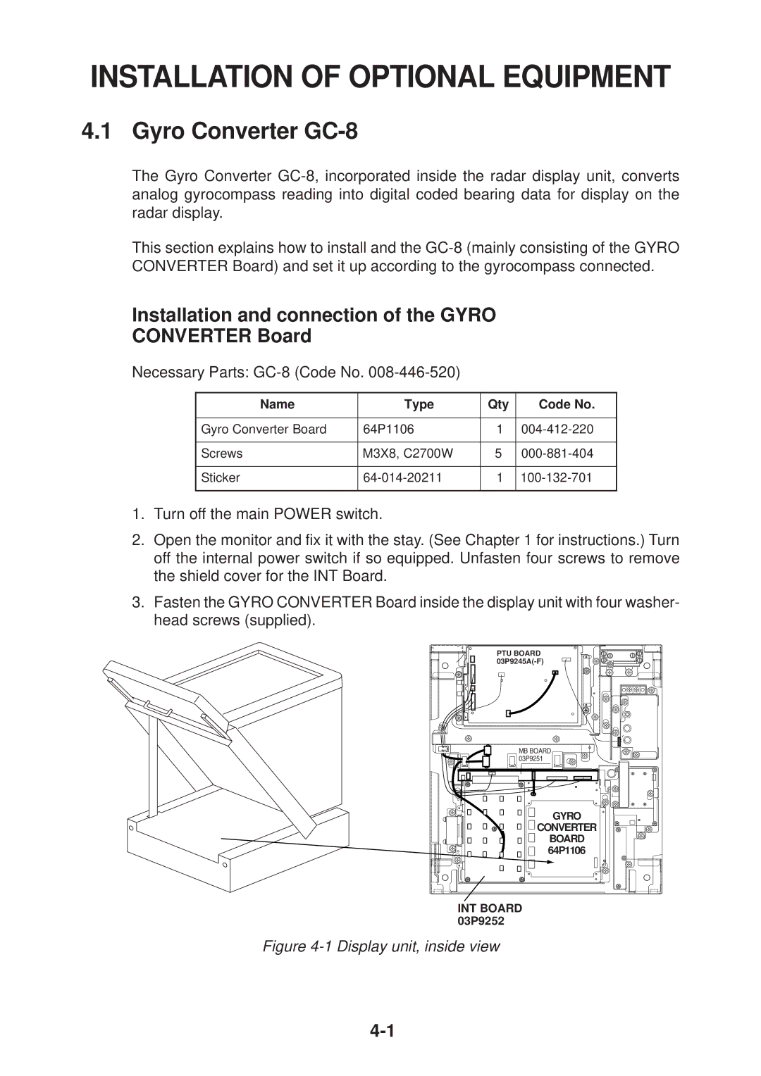
3.Fasten the GYRO CONVERTER Board inside the display unit with four washer- head screws (supplied).
PTU BOARD
MB BOARD |
03P9251 |
GYRO
![]()
![]() CONVERTER
CONVERTER
BOARD 64P1106
INT BOARD 03P9252