Innovation Series
Page
Publication GEH-6385 Issued
Page
Safety Symbol Legend
Page
Contents
Page
Wizards
Page
Appendix a Function Block Diagrams
Page
Overview
Introduction
Using Toolbox Help for Reference and Troubleshooting
GE document GEH-6401 describes toolbox features and use
How to Get Help
Related Documents
Page
Faults and Troubleshooting
Types of Faults
Fault Indication
Fault Descriptions
Cpfp isolation lost
Illegal seq state
Failed to close
Main Contactor Configuration
Speed Control Fault Check
MA pickup time
Name Type Description
Sequencer Permissives
Aborted
Illegal req for xfer
Transfer req
Tune up failed
Power Dip Protection
Than the power dip time, Power dip occurs
Should be set equal to 0.500 sec Enable
Large motor parameters errors
Operator
Required
Connections between Fosa and Shca
Power supply module failure
Card or connector failure
Short across one of the monitored power supplies
Ground fault in the input rectifier section
Ground flt alm, LP
Gnd signal alarm on, is too low
DC bus under
Ground flt, LP
Request, or Full flux request
Stopping Commands and Modes
Ambient temperature is too low
Equal to Unused
Thermal sensor input to Tfba is missing or damaged
No power to Tfba card or Tfba card failure
DS heatsink thermal sensor input is not present
Ambient thermal sensor input is not present
DB resistor package is marginal for application
Incorrect configuration of DB thermal model
Ambient temperature is too high
Stator lkg react X1 Starting react Xst
Switchgear not racked
Customer switchgear permissive not met
Heatsink thermal sensor input is not present
Run permissive lost Alarm
HtSink temp Trip
Heatsink thermal sensor is defective
AC line voltage is excessive
Value of 90% of nominal
AC line voltage too low
Suggested value of 88% of nominal
AC line voltage is marginally low
AC line frequency is marginally excessive
Frequency was at 50hz
Switchgear tripped
Switchgear defective
Switchgear opened via external command
AC line frequency is transiently low
Temperature to rise above a safe operating level
Bridge environment and running conditions cause the ambient
Pulse off time, Pulse 2 on time, Post pulse off time
Pulse tst config bad
Voltage offset
Ckt board list fail
Task 2 exec
Task 1 exec
Overrun
Task 3 exec
Ain 1 signal trip
Ain 1 signal alarm
Analog in 1 flt mode
Analog in 1 flt lev
Ain 2 signal trip
Ain 2 signal alarm
Analog in 2 flt mode
Analog in 2 flt lev
Start permissive
DBS1 Igdm card flt
DBS2 Igdm card flt
AS1 Igdm card flt
AS2 Igdm card flt
AS3 Igdm card flt
AS4 Igdm card flt
BS1 Igdm card flt
BS2 Igdm card flt
BS3 Igdm card flt
BS4 Igdm card flt
CS1 Igdm card flt
CS2 Igdm card flt
CS3 Igdm card flt
CS4 Igdm card flt
AC line transient
AC line watchdog
AC line rev phs seq
Motor OT fault sel
Parameter Motor OT fault sel
Motor Overtemperature Detection
AC line vfb offset
Customer use NC
Parameter User NC fault sel
Parameter User no fault sel
Flt
Reverse rotation
LAN alarm request
DSPx Watchdog
Failure to rotate
System ISBus error
Motor rated power, Not entered
Motor service factor, Not entered
LAN watchdog
No. Name Type Description
Frame PLL not OK
Paramters/Functions
Page
Motor winding cfg 114 Preflux Forcing
Capture Buffer
Diagnostic and Utility Functions
Diagnostic and Utility Overview
Function Inputs
Function Outputs
Variable Description
Not stopped Stopped is False. If Cap re-enable delay
Function Configuration
Channels enabled
Parameter Description
Value in Capture trig level
Than value in Capture trig level
Function description
Related diagrams
Capture Buffer Compatible Behavior
General Purpose Constants
VariableDescription
General Purpose Filters
Output = Bandwidth ⋅ Input + Bandwidth
Oscillator
Position Feedback
Integer constants
Predefined Constants
Floating point constants
Boolean constants
Signal Level Detector SLD
SLD1 compare mode = In1-In2Sen
SLD1 compare mode = In1In2
SLD1 input 1 abs val SLD1 Input Values
SLD1 compare mode = In1=In2
SLD1 compare mode = In1-In2Sen one shot
Simulator
Control Diagnostic Variables
Line Simulator
Drive Configuration Functions
Intelligent Part Number IPN
Product field
Primary Motor & Application Data
Reflected indication variables
Calculated control variables
Display meter scaling parameters
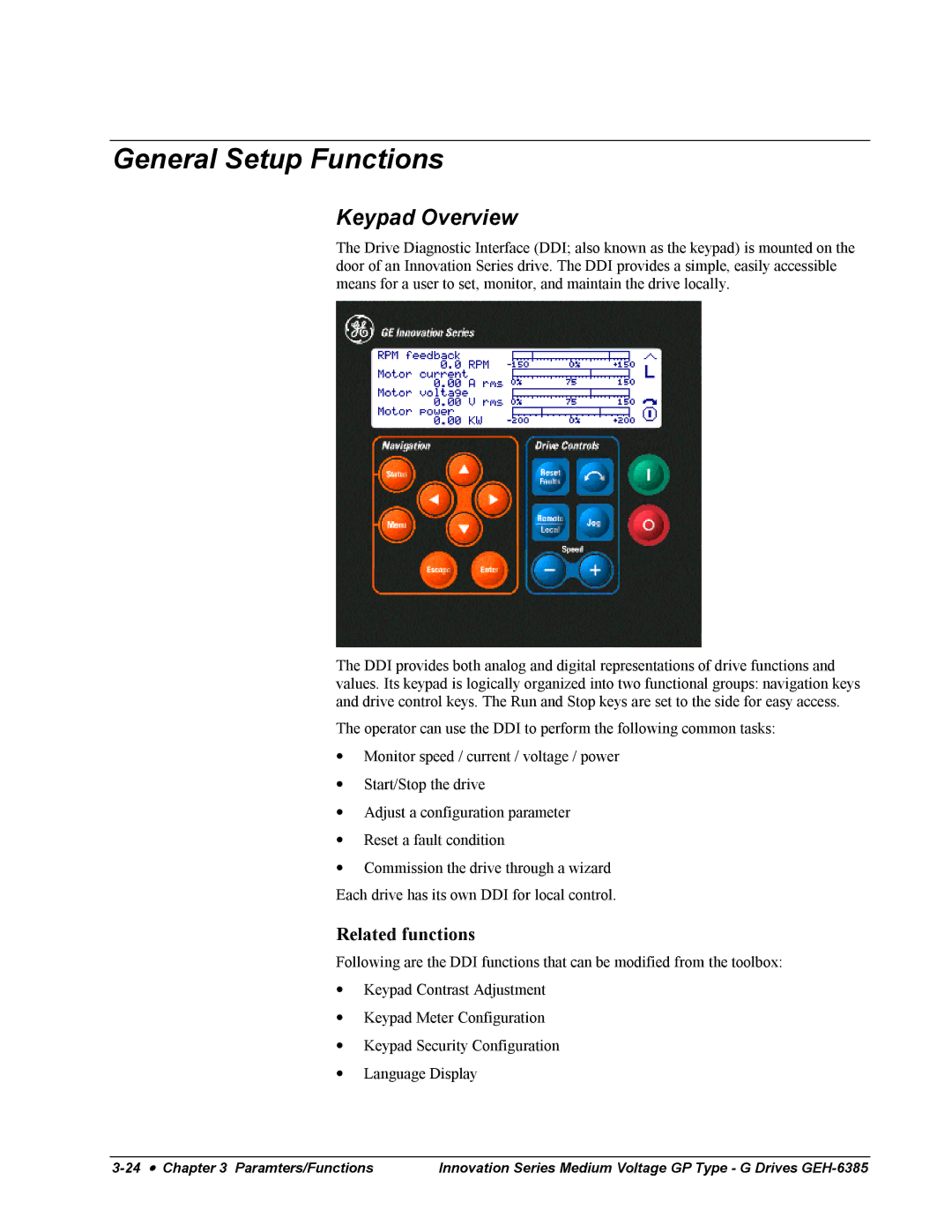
General Setup Functions
Keypad Overview
Related functions
Keypad Contrast Adjustment
Keypad Meter Configuration
Function configuration
Keypad Security Configuration
Password
Language and Units Presentation
Menu functions
Display units Length Power Torque Flux
Language Display
Analog and Digital I/O Testing
Functions
Analog inputs
Hi-fi counters
Local and system fault strings
Digital inputs
Contactor status
Analog Inputs/Outputs and Mapping
Relay outputs
Digital Inputs/Outputs and Mapping
Ctbc Output Pre-programmed function
LAN Functions
Frame Phaselock Loop
Phaselock Loop
LAN Overview
LAN Configuration and Health
Configuration parameters
Heartbeat fbk, lan signal
Diagnostic variables
LAN heartbeat trip and LAN heartbeat alarm
Frame Phaselock Loop
LAN Signal Map
Speed Reference Generation
Signal Data Description Element Type
LAN References
Speed/Torque Regulator function
Bit Signal Description
Used in the Speed Reference Generation function
Used in the Motor Control Interface function
LAN Feedbacks
Level Zero speed level
Sel
Related diagrams
Motor Control Functions
Motor Control Overview
Flux Curve
Leakage Inductance Curve
Line Transfer
General operation
Motor transfer functionality
Motor capture functionality
Motor Equivalent Circuit
External line reference functionality
Motor Temperature Estimation
Power Dip Protection
Value of Power dip control Expiration time
Faults and alarms
Fault Description
Tach Loss Detection
Variable Description
Custom User Faults
Fault/Alarm Description
Protective Functions
Fault/AlarmDescription
Occurs when Gnd current, coarse Gnd flt
Ground Fault Protection Fast
Fault / Alarm Description
Coarse trip
Hardware Fault Strings
Input signal connection
Heatsink Thermal Protection
Related faults and alarms
Line-Line Voltage Protection
Variable Bridge ambient temp
Motor Overtemperature Detection
Phase Current Protection
Parameter Motor OT fault mode is set to Trip flt
Parameter Motor OT fault mode is set to Alarm fault
Timed Overcurrent Detection
Faults and alarms
Page
Page
Transformer Overtemperature Detection
Alarm fault
Enabled. The Ground flt alm, LP alarm and Gnd flt trip trip
Alarm, Ground flt alm, LP is present
When set to Enable, the Motor Ground Protection function is
Motor Ground Protection
Trip fault occurs if Gnd cur signal = Gnd signal trip lvl
Alarm is present when Gnd cur signal = Gnd signal alarm
Alarm off
Ground flt alm, LP is present
Phase Imbalance Monitor
Line magnitude
Line Monitor Overview OvrLinMon
Line Monitor
Phase Imbalance Monitor Phase Lock Loop
Phase Lock Loop
Magnitude, AC line voltage mag
Voltage and X axis line voltage
Sequencer Functions
Fault Reset Logic
Reset select to be active
Sequencer Overview
General Sequencing #1 GenSeq1
Sequencer Permissives
Populates Run permissive
Strings
Normal stop mode is set to Quick stop or Coast stop. Also
See Stopping Commands and Modes
This parameter removes Coast stop active and Quick stop
Stopping Commands and Modes
Related faults and alarms
Request, lan to set Run request to True and at Stop PB
Commands
Request to True and at Stop PB request to set Run
Request to set Run request to False
Level , unless Flying restart is enabled
Speed reg fbk has reached the Zero speed level ,
Zero speed level , unless Flying restart is enabled
Commands OK is True. X stop request, lan must be True to
Behavior of X stop request sel. See also LAN Signal Map
Function output
Run request. See Stopping Commands and Modes for more
Sequencer Commands
Stopping Commands and Modes for more information on Stop PB
Select
Standby command
Also see LAN Signal Map
See Local Speed Reference or Remote Speed Reference for
Is used to measure the value of motor parameters that are
See Sequencer Permissives
Normal or X-stop. See Stopping Commands and Modes
Sequencer Status
Permissives
Sequencer status variables
Speed/Torque Regulator
Main Contactor Configuration
Function input
General Sequencing #4 GenSeq4
Speed Limit function variable Min speed output . RPM
Speed Reference Functions
Critical Speed Avoidance
Speed ref, pre ramp . RPM
Local Speed Reference
Speed Avoidance Zone Center Speed
Minimum Speed Limit
Avoidance function variable Speed avd func input. RPM
Remote Speed Reference
Speed ref sel is False
Manual speed ref sel is True. RPM
Speed Reference Generation
Stopping Commands and Modes signal that indicates
Speed Reference Ramp
Avoidance function variable Spd avd func output. RPM
Break point 1 and Accel break point 2. RPM/second
Break point 1. RPM/second
Between Acceleration rate 1 and Acceleration rate
Between Acceleration rate 2 and Acceleration rate
Ramp rate Active region
Speed Reference Reverse
Speed Reference Generation OvrRfSel
Speed/Torque Control Functions
Droop
Motor Control Interface
Enable req. RMS amps
Function configuration
Speed Control Fault Check
Over speed configuration and operation
Failure to rotate configuration and operation
Loss of spd control configuration and operation
Reverse rotation configuration and operation
Speed Feedback Calculation
Function control outputs
Function display outputs
Speed/Torque Overview
Speed Reference Generation function. RPM
Speed/Torque Regulator
Net gain
Error only in Torque, spd override mode see below
Between Speed reg reference and Speed reg fbk. RPM
Output
Ovrd/Spd forced mode within Torque, spd override modes
Act to Ovrd/Spd Low
Act to Ovrd/Spd High
Spd reg pos err lim & Spd reg neg err lim
Active Torque, spd override mode
Regulator function
Speed reg output is zeroed, and Torque ref input is
Specified by Spd reg pos err lim
Forced Torque, spd override mode
Sel is False, or the Torque reg stop mode is
Specified by Spd reg neg err lim
Motor ctrl alg sel
System Data Parameters
Exec time/Chop freq
Values
Motor efficiency
Functional use
Units
Motor service factor
Motor winding cfg
Preflux Forcing
Wizards
Page
Page
Fiber-Optic Test
Cell Test Wizard
Cell Test Options
Bridge Cell Test
Physical Diagram of Correct LED Lighting Sequence
Running the Test
Troubleshooting
Problem Description
Following are descriptions of error messages
Error Message Description/Procedure
Running the Bridge Cell Test
Following are descriptions of bridge test failure messages
DAC Setup
Following are descriptions of error messages
Drive Commissioning Intelligent Part Number
Drive Commissioning
Drive Commissioning Overview
Drive Commissioning Drive Units
Drive Commissioning AC Source Selection
Drive Commissioning Motor Nameplate Data
Related elementaries
Drive Commissioning Motor Protection Class
Drive Commissioning Motor Data Sheet
Drive Commissioning Motor Crossover Voltage
Drive Commissioning Motor Poles
Drive Commissioning Motor Data Sheet Equivalent Circuit Data
Flux Curve Data from Motor Data Sheet
Drive Commissioning Motor and Process Speed Referencing
Drive Commissioning Tachometer Support
Drive Commissioning Tachometer Pulses Per Revolution
Drive Commissioning Stopping Configuration
Value of Normal stop Behavior Mode
Drive Commissioning Flying Restart
Drive Commissioning X-Stop Configuration
Value of X stop mode Behavior
Drive Commissioning X-Stop Ramp Time
Drive Commissioning Manual Reference
Drive Commissioning Run Ready Permissive String
Drive Commissioning Starting and Stopping the Drive
Run request
Drive Commissioning Jog Speed Setpoints
Drive Commissioning Reference Ramp Mode
Drive Commissioning Maximum Speed References
Drive Commissioning Reference Ramp Bypass
Drive Commissioning Reference Ramp Speed Independent Rates
Related functions
Drive Commissioning Speed/Torque Regulator Configuration
Drive Commissioning Speed/Torque Regulator Modes
Drive Commissioning Torque with Speed Override Speed Error
Drive Commissioning Torque Regulator Reference and Output
Drive Commissioning Torque and Current Limits
Drive Commissioning Torque and Current Limits Uniform
Drive Commissioning Normal Torque and Current Limits
Drive Commissioning Failed Calculation
Drive Commissioning Torque and Current Limit Selection
Drive Commissioning Alternate Torque and Current Limits
Drive Commissioning Simulator Mechanical Configuration
Drive Commissioning Power Dip Ride-Through
Drive Commissioning Simulator Mode
Drive Commissioning Current Limits
Drive Commissioning Conclusion
Line Transfer Tuneup
Drive Commissioning Exit Reminder
Line Transfer Tuneup Overview
Line Transfer Tuneup Motor Capture Data
Line Transfer Tuneup Operation
Display Description
Motor Control Tuneup
Motor Control Tuneup Equivalent Circuit
Motor Control Tuneup Measurements
Panel Meter Setup
Per Unit Setup
Motor Control Tuneup Operation
Line Protection Introduction
Line Protection Setup
Line Protection Default Settings
Line Protection Overvoltage
Line Protection Underfrequency
Pulse Test
Line Protection Overfrequency
Line Protection Conclusion
Pulse Test Analog Output Configuration
Pulse Test Bridge State Configuration
Park phase Park level
Pulse phase Pulse level
Bridge State Description
Pulse Test Operation
Remaining Parameter Setup
Pulse Test Timer Configuration
Pulse Mid pulse Post pulse On time Off time
Simulator Setup
Speed Regulator Tuneup
Speed Regulator Tuneup Model
Speed Regulator Tuneup System Inertia
Speed Regulator Tuneup 1st Order Response
Speed Regulator Tuneup Speed Regulator Mode
Speed Regulator Tuneup Manual Regulator Tuneup
Speed Regulator Tuneup 2nd Order Response
Page
Page
Signal Mapping
LAN Interfaces
Interface Module Communications Supported
Parameter Configuration for Signal Mapping
LAN
Variable Mapping
Type Direction of Data
Data Type Format
Applying the LAN Heartbeat Echo Feature
Heartbeat Echo Function with a PLC
Application of Feedback Signals
Variable Maps
Real Variable Map
Reference Feedback Byte Variable Functionality
Boolean Variable Map
Ramp bypass req Bypass ramp
Lan RmpBypass
LanRmpByp
Page
Appendix a Function Block Diagrams
SLD
ACMVAC-G Inverter Overview
Drive Feedbacks & Status
ACMVAC-G Inverter Index
Digital Inputs/Outputs & Mapping
Digital Inputs Sequencing Selectors Relay Outputs
Analog Inputs/Outputs & Mapping
Drive Lan Signal Map
Status Configuration
Drive Lan Boolean Signals bits
Status
Back Back to SigMapBit1 SigMapLAN
Line Monitor Overview
Phase Lock Loop Regulator
Sequencing Overview
Index
General Sequencing #1
General Sequencing #2
General Sequencing #3
General Sequencing #4
General Sequencing #5
Speed Reference Generation
Critical Speed
Speed Reference Ramp
To Speed Regulator Generation OvrRfSel
Speed / Torque Overview
Speed Regulator Motor Control Interface
Speed Feedback
Motor Tach Speed Feedback
Speed Regulator
State
Droop
Back OvrSpTq Deadband
Motor Control Interface
Motoring & Generating Torque Limit Select
Motor Control
Diagnostic & Utility Functions
General Purpose Oscillator Constants
General Purpose Filters
Signal Level Detection
Capture Buffer Configuration
Capture Buffer
Position Feedback Instrument
Index
Page
GEH-6385 Reference and Troubleshooting, 2300 V Drives Index
Page
GEH-6385 Reference and Troubleshooting, 2300 V Drives Index
Page
GEH-6385 Reference and Troubleshooting, 2300 V Drives Index
Page
GEH-6385 Reference and Troubleshooting, 2300 V Drives Index
Page
GEH-6385 Reference and Troubleshooting, 2300 V Drives Index
Page
HQHUDOOHFWULF&RPSDQ\5HDGHU&RPPHQWV
QGXVWULDO6\VWHPV
Page
ZZZ*LQGXVWULDOFRP