Installation and Setup Guide
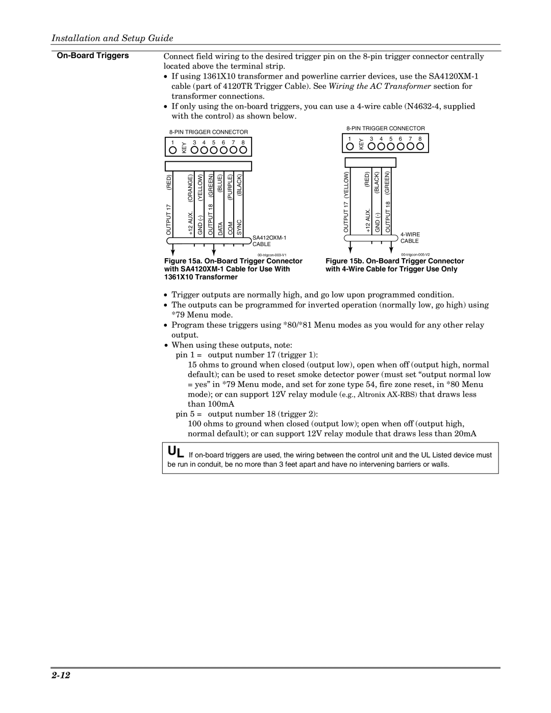
| Connect field wiring to the desired trigger pin on the | |
| located above the terminal strip. | |
| • | If using 1361X10 transformer and powerline carrier devices, use the |
|
| cable (part of 4120TR Trigger Cable). See Wiring the AC Transformer section for |
| • | transformer connections. |
| If only using the | |
with the control) as shown below.
|
|
|
|
|
|
| ||||||||
|
|
|
|
|
|
| ||||||||
| KEY |
|
|
|
|
| 1 | KEY | 3 | 4 | 5 | 6 | 7 | 8 |
1 | 3 | 4 | 5 | 6 | 7 | 8 |
|
|
|
|
|
| ||
|
|
|
|
|
|
|
| |||||||
(RED) | (ORANGE) | (YELLOW) | (GREEN) | (BLUE) | (PURPLE) | (BLACK) |
OUTPUT17 | +12AUX. | OUTPUT18 | DATA | COM | SYNC |
OUTPUT 17 (YELLOW)
+12 AUX. (RED)
GND
OUTPUT 18 (GREEN)
CABLE |
Figure 15a. On-Board Trigger Connector with SA4120XM-1 Cable for Use With 1361X10 Transformer
Figure 15b. On-Board Trigger Connector with 4-Wire Cable for Trigger Use Only
•Trigger outputs are normally high, and go low upon programmed condition.
•The outputs can be programmed for inverted operation (normally low, go high) using *79 Menu mode.
•Program these triggers using *80/*81 Menu modes as you would for any other relay output.
•When using these outputs, note:
pin 1 = output number 17 (trigger 1):
15 ohms to ground when closed (output low), open when off (output high, normal default); can be used to reset smoke detector power (must set “output normal low
=yes” in *79 Menu mode, and set for zone type 54, fire zone reset, in *80 Menu mode); or can support 12V relay module (e.g., Altronix
pin 5 = output number 18 (trigger 2):
100 ohms to ground when closed (output low); open when off (output high, normal default); or can support 12V relay module that draws less than 20mA
UL If