Mounting and Wiring the Control
AC Power, Battery, and Ground Connections
1321 Transformer
| 1 |
| 2 |
TO | |
1 AND 2 | 1321X10 |
TERMINALS |
|
Connect the 1321 Transformer (1321CN in Canada) to terminals 1 and 2 on the control board. See Wire Run Chart for wire size to use.
•Use caution when wiring the transformer to the control to guard against blowing the transformer fuse (the fuse is
Wire Run Chart
Distance from control | Wire Size |
|
|
Up to 50 feet | # 20 |
# 18 | |
# 16 | |
|
|
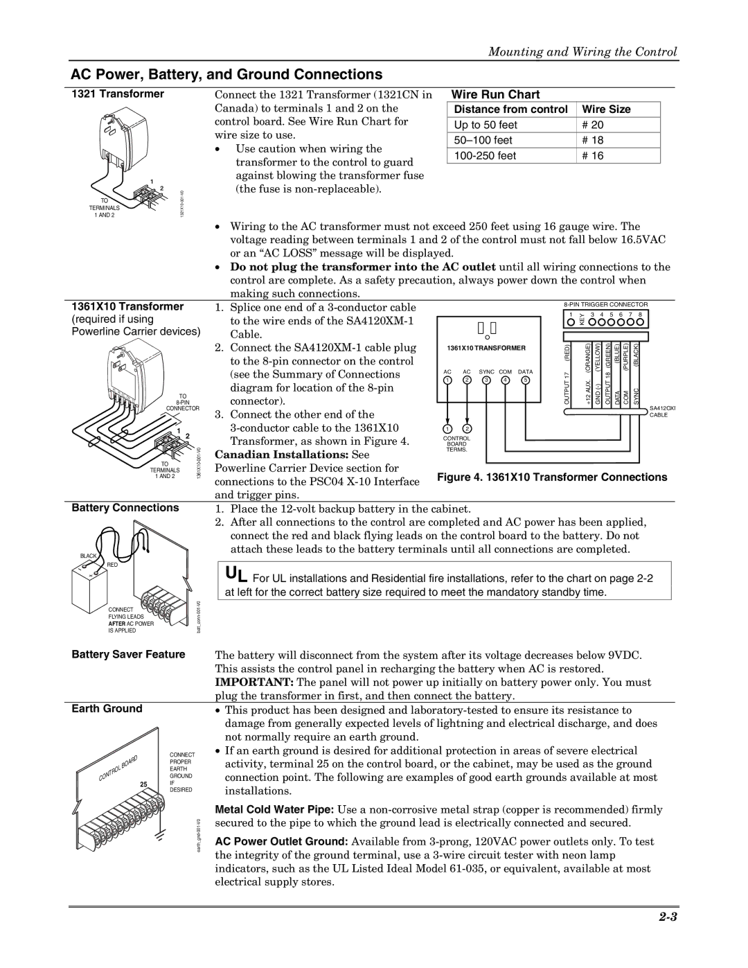
1361X10 Transformer
(required if using Powerline Carrier devices)
AC | AC |
•Wiring to the AC transformer must not exceed 250 feet using 16 gauge wire. The voltage reading between terminals 1 and 2 of the control must not fall below 16.5VAC or an “AC LOSS” message will be displayed.
•Do not plug the transformer into the AC outlet until all wiring connections to the control are complete. As a safety precaution, always power down the control when making such connections.
1. Splice one end of a
to the wire ends of the |
|
|
|
|
| 1 | KEY | 3 | 4 | 5 | 6 | 7 | 8 | |
|
|
|
|
|
|
|
|
|
|
|
|
| ||
Cable. |
|
|
|
|
|
|
|
|
|
|
|
|
|
|
|
|
|
|
|
|
|
|
|
|
|
|
|
| |
2. Connect the | 1361X10 TRANSFORMER |
| 17 (RED) |
| (ORANGE) | (YELLOW) | 18 (GREEN) | (BLUE) | (PURPLE) | (BLACK) | ||||
to the |
|
|
|
|
|
|
| |||||||
(see the Summary of Connections | AC | AC | SYNC COM | DATA |
|
| ||||||||
1 | 2 | 3 | 4 | 5 |
|
| ||||||||
diagram for location of the |
| OUTPUT |
| AUX. | OUTPUT |
|
|
| ||||||
|
|
|
|
|
|
|
|
|
| |||||
Sync |
|
|
|
Ou | S | ||
tput | igna | ||
Com l | |||
|
|
| mon |
X10 Data
TO
CONNECTOR
1 |
2 |
connector). |
| +12 | GND | DATA COM | SYNC |
| |||||
3. Connect the other end of the |
|
|
|
| SA412OXM |
|
|
|
| CABLE | |
1 2 |
|
|
|
| |
Transformer, as shown in Figure 4. | CONTROL |
|
|
| |
BOARD |
|
|
| ||
Canadian Installations: See
TERMS.
TO | 1361X10 |
TERMINALS | |
1 AND 2 |
Powerline Carrier Device section for connections to the PSC04
Battery Connections
BLACK
RED |
| |
CONNECT | ||
FLYING LEADS | - | |
_conn | ||
AFTER AC POWER | ||
IS APPLIED | batt |
1.Place the
2.After all connections to the control are completed and AC power has been applied, connect the red and black flying leads on the control board to the battery. Do not attach these leads to the battery terminals until all connections are completed.
UL For UL installations and Residential fire installations, refer to the chart on page
Battery Saver Feature
Earth Ground
The battery will disconnect from the system after its voltage decreases below 9VDC. This assists the control panel in recharging the battery when AC is restored. IMPORTANT: The panel will not power up initially on battery power only. You must plug the transformer in first, and then connect the battery.
• This product has been designed and |
damage from generally expected levels of lightning and electrical discharge, and does |
not normally require an earth ground. |
• If an earth ground is desired for additional protection in areas of severe electrical |
BOARD CONTROL
25
CONNECT PROPER EARTH GROUND IF DESIRED
activity, terminal 25 on the control board, or the cabinet, may be used as the ground |
connection point. The following are examples of good earth grounds available at most |
installations. |
Metal Cold Water Pipe: Use a
AC Power Outlet Ground: Available from