Installation and Setup Guide
Audio Alarm Verification Connections
(AAV, “listen-In”)
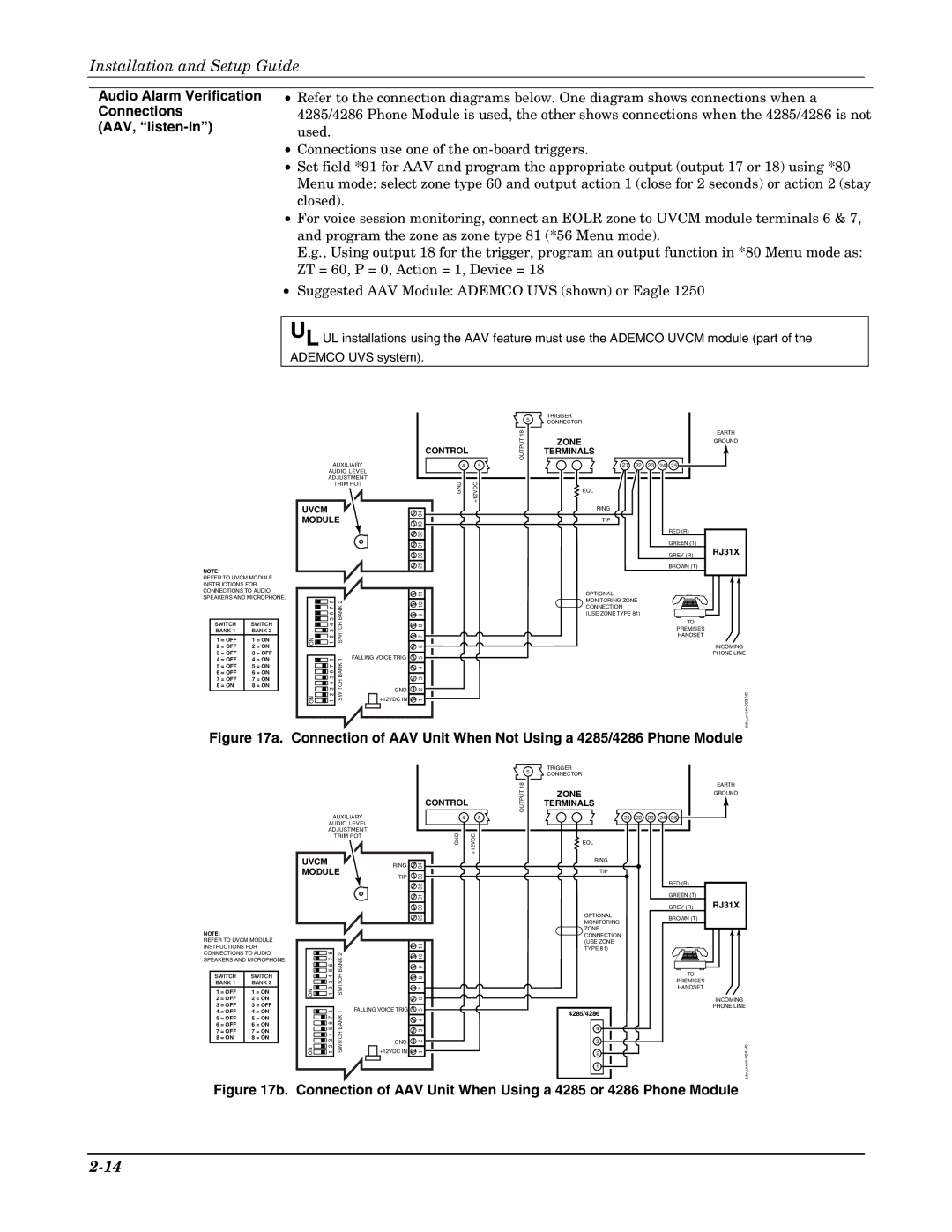
•Refer to the connection diagrams below. One diagram shows connections when a 4285/4286 Phone Module is used, the other shows connections when the 4285/4286 is not used.
•Connections use one of the
•Set field *91 for AAV and program the appropriate output (output 17 or 18) using *80 Menu mode: select zone type 60 and output action 1 (close for 2 seconds) or action 2 (stay closed).
•For voice session monitoring, connect an EOLR zone to UVCM module terminals 6 & 7, and program the zone as zone type 81 (*56 Menu mode).
E.g., Using output 18 for the trigger, program an output function in *80 Menu mode as: ZT = 60, P = 0, Action = 1, Device = 18
•Suggested AAV Module: ADEMCO UVS (shown) or Eagle 1250
UL UL installations using the AAV feature must use the ADEMCO UVCM module (part of the ADEMCO UVS system).
|
|
|
|
|
|
|
| 5 | TRIGGER |
|
|
|
|
|
|
|
|
|
|
|
|
| CONNECTOR |
|
|
|
|
| |
|
|
|
|
|
|
|
|
|
|
|
|
|
| |
|
|
|
|
|
|
| 18 |
| ZONE |
|
|
|
| EARTH |
|
|
|
|
|
| CONTROL | OUTPUT |
|
|
|
|
| GROUND | |
|
|
|
|
|
|
|
| TERMINALS |
|
|
|
|
| |
|
|
| AUXILIARY | 4 | 5 |
| 21 | 22 | 23 | 24 | 25 |
| ||
|
|
| AUDIO LEVEL |
|
|
|
|
|
|
|
|
| ||
|
|
| ADJUSTMENT | GND | +12VDC |
|
|
|
|
|
|
| ||
|
|
|
| TRIM POT |
|
|
|
|
|
|
| |||
|
|
|
|
|
|
|
|
| EOL |
|
|
|
|
|
|
| UVCM |
|
|
| 34 |
|
| RING |
|
|
|
|
|
|
| MODULE |
|
|
| TIP |
|
|
|
|
| |||
|
|
| 33 |
|
|
|
|
|
|
| ||||
|
|
|
|
|
|
|
|
|
|
|
| RED (R) |
| |
|
|
|
|
|
| 32 |
|
|
|
|
|
|
| |
|
|
|
|
|
|
|
|
|
|
|
|
|
| |
|
|
|
|
|
| 31 |
|
|
|
|
|
| GREEN (T) |
|
|
|
|
|
|
|
|
|
|
|
|
|
| RJ31X | |
|
|
|
|
|
| 30 |
|
|
|
|
|
| GREY (R) | |
|
|
|
|
|
|
|
|
|
|
|
|
| ||
NOTE: |
|
|
|
|
| 29 |
|
|
|
|
|
| BROWN (T) |
|
|
|
|
|
|
|
|
|
|
|
|
|
|
| |
REFER TO UVCM MODULE |
|
|
|
|
|
|
|
|
|
|
|
|
| |
INSTRUCTIONS FOR |
|
|
|
|
|
|
|
|
|
|
|
|
| |
CONNECTIONS TO AUDIO |
|
|
|
| 11 |
|
| OPTIONAL |
|
|
|
|
| |
SPEAKERS AND MICROPHONE. |
|
|
|
|
|
|
|
|
|
|
| |||
| 765 8 | BANK2 |
|
|
|
| MONITORING ZONE |
|
|
|
| |||
|
|
|
| 910 |
|
|
|
|
|
| ||||
|
|
|
|
|
| CONNECTION |
|
|
|
|
| |||
|
|
|
|
|
|
|
|
| (USE ZONE TYPE 81) |
|
|
|
| |
2 = OFF | 2 = ON | ON | 4321 | SWITCH |
| 876 |
|
|
|
|
|
| TO | INCOMING |
SWITCH | SWITCH |
|
|
|
|
|
|
|
|
|
|
| PREMISES |
|
BANK 1 | BANK 2 |
|
|
|
|
|
|
|
|
|
|
|
| |
|
|
|
|
|
|
|
|
|
|
| HANDSET |
| ||
1 = OFF | 1 = ON |
|
|
|
|
|
|
|
|
|
|
|
| |
|
|
|
|
|
|
|
|
|
|
|
|
| ||
3 = OFF | 3 = OFF |
|
|
| FALLING VOICE TRIG | 5 |
|
|
|
|
|
|
| PHONE LINE |
4 = OFF | 4 = ON |
| 8 | 1 |
|
|
|
|
|
|
|
| ||
5 = OFF | 5 = ON | ON | 6543217 | BANKSWITCH |
| 4321 |
|
|
|
|
|
|
| 003V0- |
6 = OFF | 6 = ON |
|
|
|
|
|
|
|
|
|
|
|
|
|
7 = OFF | 7 = ON |
|
|
|
|
|
|
|
|
|
|
|
|
|
8 = ON | 8 = ON |
|
|
| GND |
|
|
|
|
|
|
|
|
|
|
|
|
|
|
|
|
|
|
|
|
|
|
| |
|
|
|
|
| +12VDC IN |
|
|
|
|
|
|
|
|
|
|
|
|
|
|
|
|
|
|
|
|
|
|
| aav uvcm- |
Figure 17a. Connection of AAV Unit When Not Using a 4285/4286 Phone Module
NOTE:
REFER TO UVCM MODULE INSTRUCTIONS FOR CONNECTIONS TO AUDIO SPEAKERS AND MICROPHONE.
SWITCH | SWITCH | ||
BANK 1 | BANK 2 | ||
1 | = OFF | 1 | = ON |
2 | = OFF | 2 | = ON |
3 | = OFF | 3 | = OFF |
4 | = OFF | 4 | = ON |
5 | = OFF | 5 | = ON |
6 | = OFF | 6 | = ON |
7 | = OFF | 7 | = ON |
8 | = ON | 8 | = ON |
|
|
|
|
| 5 | TRIGGER |
|
|
|
|
|
|
|
|
| CONNECTOR |
|
|
|
| |
|
|
|
|
|
|
|
|
|
| |
|
|
|
| 18 |
| ZONE |
|
|
|
|
|
| CONTROL |
| OUTPUT |
|
|
|
|
| |
|
|
|
|
| TERMINALS |
|
|
|
| |
AUXILIARY |
| 4 | 5 |
|
| 21 | 22 | 23 | 24 | 25 |
AUDIO LEVEL |
|
|
|
|
|
|
|
|
|
|
ADJUSTMENT |
| GND | +12VDC |
|
|
|
|
|
|
|
TRIM POT |
|
|
|
|
|
|
|
| ||
|
|
|
|
|
| EOL |
|
|
|
|
UVCM | RING | 34 |
|
|
| RING |
|
|
|
|
|
|
|
|
|
|
|
| |||
MODULE |
|
|
| TIP |
|
|
|
| ||
TIP | 33 |
|
|
|
|
|
|
| ||
|
|
|
|
|
|
|
| RED (R) | ||
|
| 32 |
|
|
|
|
|
|
| |
|
|
|
|
|
|
|
|
|
|
31 |
| GREEN (T) | |
30 |
| GREY (R) | |
29 | OPTIONAL | BROWN (T) | |
MONITORING | |||
|
| ||
| ZONE |
| |
| CONNECTION |
| |
11 | (USE ZONE |
| |
TYPE 81) |
|
EARTH
GROUND
RJ31X |
| 8 |
| 7 |
| 6 |
| 5 |
| 4 |
| 3 |
ON | 1 2 |
| 8 |
| 7 |
| 6 |
| 5 |
| 4 |
| 3 |
ON | 1 2 |
SWITCH BANK 1 SWITCH BANK 2
| 10 |
| 9 |
| 8 |
| 7 |
| 6 |
FALLING VOICE TRIG | 5 |
| 4 |
| 3 |
GND | 2 |
| |
+12VDC IN | 1 |
4285/4286
4
3
2
1
TO
PREMISES
HANDSET
INCOMING
PHONE LINE