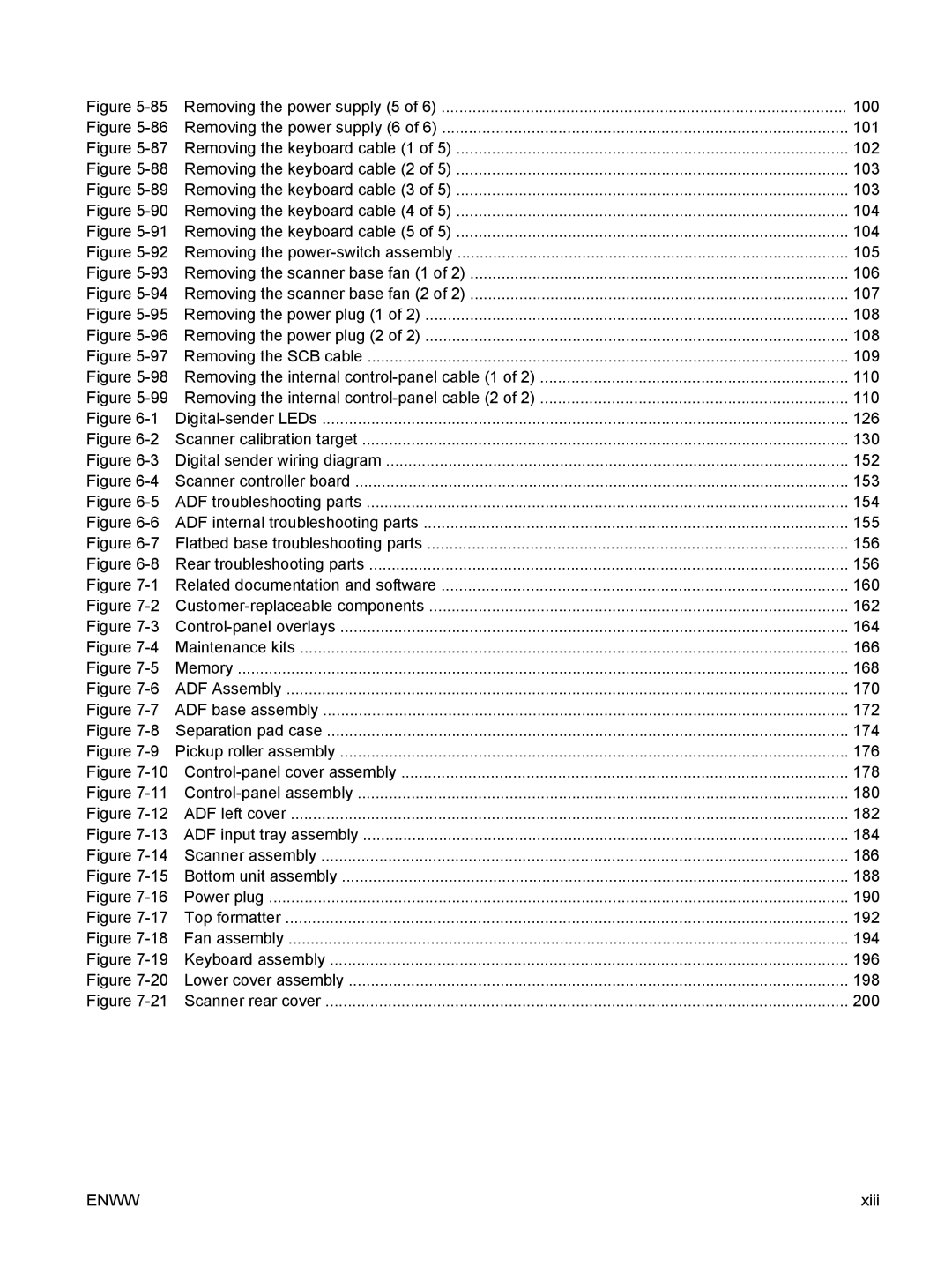
Figure 5-85 Removing the power supply (5 of 6) ...........................................................................................

100

Figure 5-86 Removing the power supply (6 of 6) ...........................................................................................

101

Figure 5-87 Removing the keyboard cable (1 of 5) ........................................................................................

102

Figure 5-88 Removing the keyboard cable (2 of 5) ........................................................................................

103

Figure 5-89 Removing the keyboard cable (3 of 5) ........................................................................................

103

Figure 5-90 Removing the keyboard cable (4 of 5) ........................................................................................

104

Figure 5-91 Removing the keyboard cable (5 of 5) ........................................................................................

104

Figure 5-92 Removing the power-switch assembly ........................................................................................

105

Figure 5-93 Removing the scanner base fan (1 of 2) .....................................................................................

106

Figure 5-94 Removing the scanner base fan (2 of 2) .....................................................................................

107

Figure 5-95 Removing the power plug (1 of 2) ...............................................................................................

108

Figure 5-96 Removing the power plug (2 of 2) ...............................................................................................

108

Figure 5-97 Removing the SCB cable ............................................................................................................

109

Figure 5-98 Removing the internal control-panel cable (1 of 2) .....................................................................

110

Figure 5-99 Removing the internal control-panel cable (2 of 2) .....................................................................

110

Figure 6-1

Digital-sender LEDs ......................................................................................................................

126

Figure 6-2 Scanner calibration target .............................................................................................................

130

Figure 6-3 Digital sender wiring diagram ........................................................................................................

152

Figure 6-4 Scanner controller board ...............................................................................................................

153

Figure 6-5 ADF troubleshooting parts ............................................................................................................

154

Figure 6-6 ADF internal troubleshooting parts ...............................................................................................

155

Figure 6-7 Flatbed base troubleshooting parts ..............................................................................................

156

Figure 6-8 Rear troubleshooting parts ...........................................................................................................

156

Figure 7-1 Related documentation and software ...........................................................................................

160

Figure 7-2

Customer-replaceable components ..............................................................................................

162

Figure 7-3

Control-panel overlays ..................................................................................................................

164

Figure 7-4

Maintenance kits ...........................................................................................................................

166

Figure 7-5

Memory .........................................................................................................................................

168

Figure 7-6

ADF Assembly ..............................................................................................................................

170

Figure 7-7 ADF base assembly ......................................................................................................................

172

Figure 7-8 Separation pad case .....................................................................................................................

174

Figure 7-9 Pickup roller assembly ..................................................................................................................

176

Figure 7-10Control-panel cover assembly ....................................................................................................

178

Figure 7-11

Control-panel assembly ..............................................................................................................

180

Figure 7-12 ADF left cover .............................................................................................................................

182

Figure 7-13 ADF input tray assembly .............................................................................................................

184

Figure 7-14

Scanner assembly ......................................................................................................................

186

Figure 7-15 Bottom unit assembly ..................................................................................................................

188

Figure 7-16

Power plug ..................................................................................................................................

190

Figure 7-17

Top formatter ..............................................................................................................................

192

Figure 7-18

Fan assembly ..............................................................................................................................

194

Figure 7-19

Keyboard assembly ....................................................................................................................

196

Figure 7-20 Lower cover assembly ................................................................................................................

198

Figure 7-21 Scanner rear cover .....................................................................................................................

200

ENWW

xiii