Tt,,,,t
Muitimeter
Hewlewpackard
PrintedAPRIL
ManualPartNo MicrofichePartNo
Tableofcontents
C0NTENTSGontd
RABLEOFCONTENTSCont,d
Listofillustbations
ACAdiGüffi
Diagram Äl,il ?7l+eatic ?rorr
PorariryR,tüä
Frz
1lNTBoDucTl0N
12ACCESSORIES.AVAITABLE
0PT0NS
SPECTFtCATI0NS
14INSTBUMENT.AND Manualidentifica T I O N
Lo . t
35+o . os +o . o2s
Oo7 .005 .0m
Contd Specifications
8 1 5 0
O07 .oo5
00fiv
SpecificationsCont,d
1000.0v
24hours23o 10c
SectionI Model34904 GenerallnformationContd
DVs/u
Vin = vs/H rl
Dvs/H
NTR0DtCTloN
REc
INSTALLATION.OFOPTIONS
Installation
BenchUse
LsolatedData0utput0ption021-hp-111ZlAl
29INTERFACE.CONNECTIONS
Option050andOption060
Data0utput0ption021
RemoteGontrol0ption022
Fc ö
SectionII Model34904 7N i 3i -s t** JrJü,1t
OPTtoN021
5 E E i F = =
REMOTEINPUTCONNECTORJ7
2H* F EI = 6 s i ä 2 qd E ? 3 5 fr i F 3 ä
= ! 9 i l
GeneralPurposelnterfaceBusConnections
RearInput
Cablepart NO. Length
10631A 6 3 1 10631C
GPIBBUSCONNECTORJl2
GeneralPurposeInterfaceBusConnectors
9 9 f
Outguard
Sample/HoldConnections,0ption040/045
TriggerConnections,GPIB0ption030
S7-30360-37s
Repackagingforshipment
D e l 3 4 9 0 a For J7 is -hp- Part No -0084 Amphenol
SectionIII Model3490A
Instbumentcapabilities
WARililG
13FRONT.ANDREARPANELOESCRIPTION
15MAXIMUM.INPUTVOLTAGES
Turn-OnandWarm-Up
I7 . Generaloperatinginstructions
Guarding
FloatingMeasurements
SELF.TESTOPERATION
Resistancemeasurements
Acvoltagemeasurements
OutputSignalsandLevels
60.0hmsSignalVoltageandCurrent
InputConnections
62.0hmmeterSampteRateandBesponseTime
InputSignalsandLevels
InputSignalRequirements
79.0utputSignals
Data0utputlsolation
030
GPIBBusSignals
SRo
DAC
103GPIB.Controlof3490A
101Talk.0nlyNoController
RÄi+ -cg- lL
L l
To7
AddressCodes
Asciicodecharacter Binarycode Octal Code
A R a C T E R
ProgramCodes
2 3 4 5 6
USE
F D
Ldav
349OAand
Printerand 3490A
Will acceptdata
Printerwill
GPIB0peratingExamPle
I X E D N I 1 J
Ooü 0 f R \ r @üoü@f E \
SetsLREN LOWon bus
\tD?u6,.. TlE,, . ?5V
136Controlby.MarkedCardProgrammer
To haltprogram,press
SroP l CMD?U6 OUTPUT13,30 ..M3R7F@E
Or o o l 4 0 z o
349OA PRoonnvr LrrruE,ir
27 l
F r
160Sample/Hold.TriggerSignalRequirements
158Input.SignalLimitations
152Special.S/H0peratingGonsiderations
156Guard.ConnectioninSample/HoldMeaurements
O40 O20
165Initiating.Sample/HoldMeasurement
OtherOptions
040 030
Typicaltimereouiredto SETTLETO1 %
173Using.theTrack/HoldMode
200
1000v
M EO F S / HT R I G G E R
Tnputvoltageat
Voltageactually
Measured
V e
179Using.theAcquire/HoldMode
T a Vc-vs
T s
RatioMeasrementProcedure
182Using.50Hz or 60Hz PowerSourceOptions 050or060
$184.RATIOlfleasurements0ption080
$186.ExternalBeferenceVoltages
Model3490A
ßüy
4I . Intboduction
+3 . Generaltheoryofoperation
RangeandFunctionControl
Display
+19 .DCANAL0GCIRCUITS
LnputAttenuator
BoottrapCircuit
SwitchingCircuits
+23. DCAmPlifier
+25. OCAmplifierGain
Ls, ys
Otui
SectionIV Model3490A
Rt-- c-++
Integratorcircuits
Dual-SlopeIntegration
IntegratingAmplifier
ZercDetectAmplifier
L44. x 20Amplifier
52AC.CONVEBTEB
ACAttenuators
HmmeterPowerSupply
Ohmsconverter
CurrentSource
HmmeterReference
+70 ISPLAYASSEMBLYFigure
InputProtection
DisplayUnits
Buffers
DataGounter
TimingCounter
M I N G
R0,0m
10. Block Diagram,Main LogicASM Flow Chart
Model3490A Tl-90.AlgorithmicStateMachine
11. Block Diagram,Main LogicCircuits
Enaele P U T S Enable Oualifierinput To ROM
105Input.PolarityStorage
TransferandZeroDetect
+II7 . Referencesupplies
+il5. DCSWTTCHNGLoGrC
+ I 7
RatioMeasrements0ption080
Powersupplies
+128 .FBONTPANELS1VITCHING
+ t
134Logic.Test,No.l
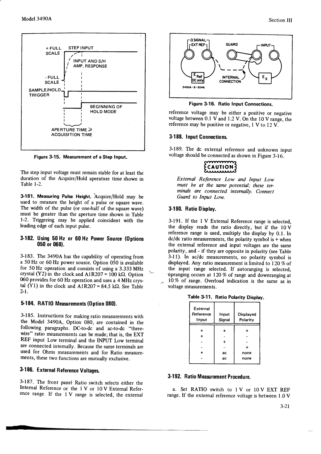
+I32 . Self . Testfunction
Polarityin Ratio Measurements
G H
+137.10V RangeZero,TestNo.2
TurnoverError,TestNo.3
+143.0.1VRangeZero,TestNo.b
4145.x .01Atten.x, 100Gain,TestNo.6
+158 .DATAOUTPUTOPTION021
+r9
4t74.REM0TEC0NTR0t0PTtoN022
LocaURemoteFlip-Flop
+188.ShiftRegisters
DauFlag
198GPIB.System
GPIBSystemOperation
+2r
Figwe 4-23. WaveformslllustratingAcquire/Hold Mode
+212.SAMPLE/H0tD0PTl0Nll40or045
216Acquire/Hold.Mode
Sample/HoldAnalogCircuits
Too
+23
@ n z
Roo
Ja+z
Compensation
TooK
228Sample/Hold.LogicCircuits
Flgure4-27. Sample/HoldLogic Block Diagram
+25
Lye e outpur
512 615.0 1000v 124.4 154.O
DC Amp
External
Exterml Hold H Hehs
Page
Ortoroo OruY --Jl
Figurb4-30. Sample/HoldMeasurementSequence
Waveformsarenot drawnto timeo, o,,rnI?lt
Example of TRACK/HOLD MEA Surementseouence
Integrator
RIOLD A1 bHOLD B r l l
I-r Gort +prr2zrs.i Qrs Sre Ero-+ 3r4 Zra Orr
10kn
RecommendedTestEquipment
Recommendedtesteouipment
TNTB0DUCTIoN
Performancechecks S7. Performancetests
$9. Dcvoltmeteraccuracytest
@ \ d
Performancechecks
15OHMMETER.ACCURACYTESTS
L6. PreferredMethod
AC Voltmeter AccuracY
OhmmeterAccuracy
1OO
ACCOMMON.MODEREJECTIONTEST
Pebformancechecks
Dcvoltmeterinputresistancetest
S24.ACNORMAL.MODEREJECTION
Model3490APERFOBMANGECHECKS
Rrr-rrr--r
O o ?
28AC.VOLTMETEHINPUTIMPEDANCETEST
Test Oscillator
@ \ - O @ @ o o
MU L T I M E T E R h p 3 4 9 O a
6 5 2 a
RATI0PEBF0BMANCE0ption 080
Perfohmancechecks
$38. DC/DCRatioAccuracyTests
+ 100.000
ExternalReferenceInputResistanceTest
S41.AC/DCRatioAccuracyTest
45GPIB.0PEBATIONALCHECK0ption030
Ext Ref Nput Lnput Display Limits Range Voltage
Lo v Ranse
It l l K o
PERFORMANCECHECKSModel3490A
1000kO range
+tll
Fj Fl
Fä il Ir fli
IiI
Ii tti 1üj Li i l
Rf,lIr i5i 1.+ri
R * ! i t F T
I i , Il
It I l L1,1ti
Adjustment
Procedures
$ 51 .ADJUSTMENTPROCEOURES
Powebsupplyadjustment
Dczeroadjustments
Model3490AAOJUSTMENTPROCEDURESSectionV
$57. Referenceadjustments
Dc standardhp- 7a0Bis requiredfor these
$66. Ohmmeteradjustments
69SAMPLE/HO.LDADJUSTMENTS
73.0ffsetAdjustment
Model3490AADJUSTMENTPROCEDURESSectionV
$75. DielectricAbsorptionAdjustment
Dc standardhp- 7a0Bis requiredfor this
Ratioreferenceadjustments
Aojustmentprocedures
Lqe
Orrra
ColTect
Adjustmentprocedures
Testrecord
Perfobmance
001v r 0.oo1v
Performancetestbecordcontd
LO.V l O V 1 0
+ 1 2 . O O O
50000v Ooooov 120000v
Performancetestrecorocontd
Ext Ret Fngu V 1 0
00000v 10.üoo 12.0000v
Orderinginformation
Intboduction
NON.LISTEDPARTS
Proprietaryparts
Reference HPPartNumber
Otv
Description Mfr Mfr PartNumber Designation Code
B l e 6 1 . R e p l o c e q b l eP o r t s
B l e 6 1 . R e p l o c e o b l ep o r t s l C o n t d l
Rcor-@4o Leol-m4ol\
Model
Reference
Oty
HP Part Numbel
B l e 6 1 . R e p l o c e o b l eP o r l s C o n t d
B l e 6 1 . R e p l o c e o b l eP o r t s C o n r d
B l e 6 1 . R e p l o c e o b l eP o r t s C o n t d f
Qty
AI R3A AIR3@
28480 2a4AO
B l e6
R t s l C o n t d f E p l o c e o b l e
Aterei alnz?
Model 3490Ä
OtyDescription Mfr Code Mfr PartNumber
B l e 6 1 .R e p l o c e o b l eP o r t s C o n t d
DesignationReference HPPartNumber
Oaa+-rrtt $
B l e 6 1 . R e p l o c e o b l eP q r t s l C o n t d l
Reeo-sg
DMT4LOON
R5ß7
B l e 6 1 . R e p l o c e o b l eP o r t s C o n t d
A5s4 Sli2
Aoaroassyrehotejuxper
Cr r?21
Oty
CB a72l
?5r-orlo
Description Mfr Mfr PartNumber DesignationHPPartNumber Code
Otv
28aao
2A480
Re*-ooar lil
B l e 6 1 . R e p l o c e o b l ep o r r s C o n r d
Zroo rzaaAA
Orzo-oo+o
Reference HP Part Numbet otv
Description Mfr Mfr PartNumber Code
Designation
B l e 6 1 . R e p l o c e o b l eP o r t s C o n t d
C8 ?2rl
B l e 6 1 . R e p l o c e o b l eP o r r s C o n t d
C5 22at
DrT4LOara
T u 2 I l 5 u
ModeI34904
AI3CR8
O O E B R E a K D O I I N
Model Section
R 2 r
Caeleriaeon Ottgiitrdrei Isolatii Boardassy
Cableribbon
Heiioi
A22API
600
B l e 6 l . R e p l o c e o b l eP o r t s l C o n t d
400
A27RI
A2ARI
B l e 6 1 . R e p l o c e o b l eP o r t s l C o n t d
Rfxd Cotp IOK OHX IOI L1Y
OBD
Z9cl 2 e c t 429C4 29C5
OHn 1trÄ 1/4W
I P l2K OHI lot
I I P 22K otr lot
A3IU3
A32RI
Mfr Code
Reference HPPartNumbet oty Description Designation
A34YI
2211 2211 CB
A39RA
2A4AO 2S4AO
Reference HP Part Numbel
B l e 6 1 . R e p l o c e o b l eP or t s C o n t d
T20/o
EIlrDtrs PosT assY
B l e 6 1 . R e p l o c e q b l eP o r t s C o n t d
IcxssIs assY
284r0 2a+ao 2A480 28480 2g4AO 284aO
Description Mfr Mfr PartNumber
HPPartNumber
Reference
Xo1
OtvDescription
Reference HP Part Number Designation
Mfr Code Mfr Part Number
B l e 6 l . R e p l o c e o b l eP o r t s l C o n t d l
MP37 MP23
SectionVI
MP7
Designator L M P l a MP1B M P l C MP1D MP2 MP3 MP4 MP5 MP6
29500043
318x32
ACCESSF0RSERVtCtNG
Pbeliminarytroubleshooting
Troubleshootingtrees
Powersupplychecks
13DC.ANAL0cCtRCUtTS
TableT-2. PowerSupplyJumperWires
AZAsemblyExchange
DCAmplifierChecks
Nlii
DCAmplifierSwitchingGircuits
A N D 0 V L E V E L S O C C U R a T
I G G E R S C O P E a T a 1 T P K , + S L O P E
33AC. Convebtertroubleshooting
3I .INTEGRATOR Troubleshooting
37OHMS. Convertebtroubleshooting
21A. -to-C0NVERSt0ND CtBCUtTCHECKS
Logictboubleshootingsuggestions
Displaytroubteshooting
ExternalTriggerCircuitGheck
65SAMPTE/HOLD.TROUBLESHOOTINGTREES
59SAMPLE/HOLD.SERVICING
Accesto Sample/HoldGircuits
03490-006M
22000139
03490€6528
O3490-27301
75SCHEMATIC.NOTES
RATIO.TBOUBLESHOOTING
AmplifierZerc0ffset
+ 5
Logicgatesymbols
Truth Table
Truth Table
U 4 o t
SectionVII Model3490A AlphabeticalListingof 34g0A Mnemonics
Alu401 Rexe
Nrsc
= l
Tl-l
IaFeV-pF
Guspb b l
Page
I1Lgji
Rtl7-r2
I1glil
Iai ott *nn !drp6 ltnt. rync,+.1@
+ Input
Ll?Qxl c207c2or
@ @@
3ttr . n
? 1 t 6 1 l 7 + T i + ?
T E
UiL
Q208
YES
3 6 m s i 4
Q2O5 t1 swith
AITPK. +
Ratio INT
O2or
R317-1
0205
0208
RaG
+.JL
LfT
Q9e
299A
See Notes
14,iä
Ffi
?rSlI
Ov1--t==- -l6oms
1s17-t6
LOomsF
R7vl l
Tlrtlt Wath AnDr
Llo
Rd 15 ot Altrt. JFuldbo+5V Lm r . tt
Tlrtlt Wath AnDr
Troubl .. hoor A7Ot ?CRIOüa ll
R7l7-r8
Eff#ri
#lsriieo,e*l
Iub s!!h
I l
T9lt
DisplayTroubleshootingTree
T l
L i l t l
=LJ. L--l
ITa --- it
TEv
Ru*rffifc
O 1 o
NVW
Page
Lirlt?lt..it \- toresh@rArur5 aIut1 J
3t,1
O24 oo24 @24 oo24 9032 oo24 t.o24 n 4 n2.4
Lop
Displaysholdread
Initiare 6 mre smples
+ 10.oo24
+ 60O0.xxOL
S l . l
Tl=l
LDr s
€@CI6@@e#ffi
S +
+ 5 n-s l r
Ttj ,o
Otuu U.T,J,l,,t-t
+ i O 5 4 s F
+5 ms-l
2317-1
10. Logic Clock TroubleshootingTree
L sl \f -Jt +1 l
THttttffi
$E B?tr+1HHHLE r r r r r r r l
+ft$b!too
Us-l Url
L- l l---,.l
Llt
5 a
Jtr2cr
Llj. -zooms*#ll-+l.l-r
\ÄÄ
+- zoomsl
Pulses
Ea . f
Ti1i
1-t.i1
= b3mtl
2s17-26
Ffi
I. J?
At7A2
Gig
NOI€S
Tlu2, a t1u3,Arl
Th.-l
=rF
+ 5vr-r
1o.4ßF
RtN*16t12
Figare7-12.RemoteTroubleshootingTree,Option022 2717-28
+s-Yml
+o.cF
9 0 D- 3 3 8
Start
338r
Hffi3
Cauil oN . l
13. GPIBI/O TroubleshootingTree,Option030 2917-30
Hp Porl No O Rev . B
Port No V . C
Öl--.le
A27KI Shoulo 8€ CLOSED.SET SAM
Correcn
D a
SET S/H Sayitch to TFACK/HOLD
Main CIRC-IIT8OAFO. Shouloae
CABLESCORRECTLYGO. to
Oft-.*l
T3t17-32
9 0 D 3 4 3
HOLD. M€ASURE Voltage AT
Hp Fort No -66527 Rev.B
I,l
Port No . O349O Rev . C
To A2 X E
Eogeof .AIPLIHOU TRIGGCR!G
8Ap-crtot awrcH To rRcx
Iore Sigial G€S High
Tote
JüJ
Ffi.f-L
RävnG.iir
3 f r a
3490-0
73317-34
Hp Pott No.O349O
P U T
LOW
EXT REF TPC
LOW
P U T TPC
High
TPC A13CR6
TPC
+ l 0
G H LOW G H LOW H I G H L O W
16. Ratio TroubleshootingTree
A33
A31 Rearof Instrument
A12 A17 A22 A11 3 or A36 A34 A35 A30
I11
€ d
Ral
111
Jj,i @ @.6r
+++F+r@a
#Jälslt*tJl=l
Rö*et e J l
Üä,ierispgglg*@ WEE @D@@@@@ ++++++++f++Evvvvvvvvvvvv
+ ö
EfEU
737
18 a Block Diagram
WüE,Ä,li
FP?fä
REFEBETTCEDESIöTATIOtIS
CoKno
Lli-@@@@@@@
LelQg
Ilgt,,a ,,r.i.li
Q l
Overloadprotection
Hovpoverloaoprotectionh
A R D
T6azt
Bootstrap P L I F I E R
RuorerzV AA
A M P L I F I E R
\+l
Feedbackattenuator
? z e 1 2 z
Z r z l
$E?
391740
Zl-----l
@$Y@ Y 6ö Ff$$**H++
9i czo1
?o70 f
IRrr5- l .FrrBll- l Pt lP r f
FRoM Sv---*-l---5v
Lp/0 Al I MArNcrRcurrassEMBLYo34so 6650r +ov +rov
SueeLv +rzV ----d-tr-E +tzv +5V +5v TZV TZV ---b
C203 o.33
1411742
Zero Detect
T7v- t7v CR202
Tf,rl
Faq h-,,dn
XPf*trt*r+9e . E
Rblhb-l- --,1
Ott,t
Ffie
Itu
?-rv
+REFERENCESUPPLY
F E R E N Cpeo L a R I T YL O G I C
V E R T I N G P L I F I E R
Figr
U3o! ----t
7431744
F E R E N Cpeo L a R I T YL O C I C
V E R T I N G
Rrr Nililji
ß?i-,- *$1,sE1iV
Llt ri.ä-i.i Ffi
?ääijO * 9sö $
Powerfrom -5v---dä-!-- IP*333
O*. n i!g!?ifiJjscaNBH
3 1 6 t
7451
\------lJ
Siorra
Timingcounter
I3g.i
P .L.iU.B Ll 11
Stir lT- Il
Äiiiirr lir,il..1 Ilir ! o @ @, = T-T
Rua --I xma
I3Bl,J-r
Nne--r LHur
R N O N C L E a R R C U I T
Röüärrrr-l
3bEi,?#
?5Silij
FRoMU6iIä
L o
Otonrä
L8d,tshäl 3Yä1..dP
Tansferenableh F R O MU 9 2
A N S F E RA N D Z E R O D E T E C T
P U T L a RIT Y Storage
Il J
Pp* @@@@@@@@@@@@
E i i + + i +
@@@@@@@*späsw
6ffi-l
IlJ**io**l.Io,l
Lffioi
Fää-.trto-*tot
Soupr-Ezro-r-oirfr
Soue.e,.oloieftil-l
74917-50
Fs-rLErHoLDpi6il-l
\ 9 t r l = l
+ q r
Hp PortNo O
\ R l
Rr,rorHER
Ig t31,.9uIGgARo
220V Toov T20v 240V
Regulator
Ouiro
TOAa
Grppry Optrorr Assr Ozot
+ l 7 v Regulator
5117-s2
+3OV Regulator
3OV Regulator
Hp Port No.O349O-66503
REV . B
BCD
Roaru4oreil
Enable
=i33SfTHr-+
Polaritydisplay
U4,uro
Polaritydisplay Enable
A N N E R a T O R
Scan Decoder
Io*F
Figwe 7-27. SchematicDiagram,Display, A3
S3l7-s4
Ra FE FA FB
= E
Componentside
R C U I TS I D E
Q N a e r , *I .l ,*l ,i , ,ElllRANGEIH**iL
S l r q r l
Ror..RArEcH,rrr., tfl*l
R*.,j#
LFaN6E-l s4
Ss -s6
LFUNcroNl
Test
+ + 6 D
=sÄl---l
Ll l
L-sJ
A6T* .* r*.* *-..u
V, cK+
+tzv ---fre- +rzv r l +5v --+r5- +5v
Attenuator
Oot
Converteramplifier
+ r 7
S7l7-s
Figwe 7-29. SchematicDiagram,AC Converter,A6
Filter
Nc corvepreR ourPUT1
Drluod O6t9O-20999
Ofqlrod 06t90-O999-l
UeacpalpueHuoll3as
Ifl3?5fö*co,c
Ei-tr
Flt Bl,,J.li,i Vrx Norlrr,rn CNn.Norr vH
GttornrvsnHounor Rsnxo
LN3UUnC l3unos
Arn8rg Crlerueqcs Surq6 Urur8erq RelJouoJrV 0vLl6s
U3t3NltHO33N3U3J3U
Ssoucv 39N lmdNt
? ? T
42242
A22Al
Fff.ItTrsGooo +l--.r
1M1 ASSEMBLY 3äYäiäT?lTl-?.1..i
Rxrnrr
+l8oyJl,flylo
Tl,,t1
SAMPLE/ Hold Triggercircuit
Wro
7411142
+f-!-l-tr-ourcuaRo
Ro ooroorrr coNNEcroRJ6 Ro *.or. ,*r* coNNEcroRJ7
Älll
L J J l
Ur-l
5 a
LEoR Eon Fil!Täläf
ÄX?,3,.o
Q U E N T I ALO G I C
Freque
Data Multiplexers
Logtc Clock Frequencydoublerdelay
+-n
Outguard
9 \ I C E N I a N ri fr. F
# , . , J
DAraFLAG
2eI
+5vr---1i1+4
I G a N E
W S H I F TR E G I S T E R S
Guaro
Oi---qo
+ 4 l
Zfu*-rrot
74317-64
At7
7 a
Oo-1 Al2 Hp porttJo,03490-66512
LO REMoTEnruruurrcraron
+ s
LOCAL/ Remote FLIP- Flop
LOCAL/REMOTE
RHs tl su31sr93u
= r
AJtlilo-*il1.iI
Lockdelay
91 .-Ct
FlIto*.- -7u u5
Rns+
\ .,- I \ Onr9nvu0 rdtIlnn-u3x3
NBId
Ouvngmo l,ssv
Z r
To A2 C D E F H J K L
Hp Port No
14,0o*%ÄäuJJii
F8fi8
L8 PRbou%u
T8 iäB?i
If U8 is BAD.OUTPUTWAVEFORMS
R c * o lI l r g S
46.4 K
Will 8E Loadeddown
747l7-68
?? l9Li9i.-.?
Rt\u
? * t o RrreenrroR
U l H
Porf No . O349O Rev . C
€l-----19
Iäo*,j.,lj!,j
Ori
TABu?,.ffiIi
O 1
M P L E /H O L D T R I G G E R CI RC U I T S
Bs-u
A L I F I E R M U L T I P L E X E R
Hmtb
?.46,f
?6Tr%r,i
74917-70
CRs
Jil
OEo o r a o r B orc o r o o t M
SDo
I N E
To S/H Logic
COPYRIGHTt973 by Hewlett Packaro
Dislay
LOCAL/REMOTE $ Ection Aage Clocks 5 Lines
Ouoorn REcErw
FC Company
36.BlockDiagram,3490AGPIBVOCircuits 7117-72
Hp Port N o . O 3 4 9 O 6 6 5 3 4 R e v .A
L24-----r3-l Or5
Hp Porr N 0 3 4 9 0 6 6 5 3 6 Rev a
N D
Orurr9iorrrol98rfiilV
Tot
RnvH ornv H Or6rnrv CucxJ Rvu . Hccr
RvrrxrJNorroNnr Rfillj
Sosr
Ertv Rzr Slinur
Tt lrstl3ssv
83x3ldlrln$l
Uui-,f +sv
RaI ,tuf,r 3+r7v
S K
Tzv--Le f -rzv
O r
?,il9Bälooo
+Fol
?oti.lä?fr?ox?Ei6q*1Eefi&x?ot
R l
U 1
Port No
Uu +sv
Ä33a
Rl?ulF5-ß-olqrroil
ETGpr 03490
GLA
Ä3a
Lre a
HRsr o
? l
7517-76
RfbÄiÄÄ 2 -ixaorJ
Or.nroro Orrl assv 2 l
Ri------l
432
L3-JrIt TLr.sl-------l
Hp porr No.03490-66532Rev a
20A%ll?i8*o1lg9lRor-oos---Lrs-r-oosl
Lrrx i--=
22LEoP-rJi,19#E8ffi0 22fr,.#.!äi$o LsRe--1i-,r
20 loo.tfliloX!3VotoLRMrl
Iä.ggx3!.zz
I I z
Ooorf
Roro-r-,@
Fruox
CvvH r
9I3?ü?591.ZZ
Ilr
Ilo Sa-oosl.J?il!.31..Ä.OZ
Nzr Rnzr RE+
Hp Port No.oi49o-6653t RevA
TT----l
R K o
CR3 CR5
Rvvr
Oo-1--5
Wououvngrno
+lvvH Vrvossv Ovvx-+
+ 5 V r
+rzv1
O L a T E D P O $ / E RS U P P L I E S
+ l z v l
Ztisv Orur
Your
LsoroH
IsoroH L n OZssv Rorol
N0rrcn00urNll
SruvdroN Orlsr
L0Nvl3 33Nln0ls
JzztyostorJzypxJ
Zzlosro
TluzvtJzv Inzvlrncrrc Ppv Pue gluzv ot
Jeu
O ö t
TlzGszzov
Eää3
Ii ä ä i
Äää
Arnorg LLVrueroerg Clpuaqcs Reslquassv.plgglLoV!Z!oNpueol
ÄffiäHi!,äffT1Hiä1s,äTffff-nill-,gl
Burur5
A8dqdw
Toot lsn tosütünlYrnilYw
Pulsl
Owl v N n l v r r n u r u s
LodrlaH
ÄJnuf
Iutdd!q\Nf
Opuntas
LqunloC IEIuqcaI
L a a J o J d
99.68r
9er rtl9
Sttvs ? Tctuts s3crJjo Otrriln Srlvls
VovNvc
Rturtt
Leiol
RrlanD
Lvulsnv-vr
OüvxgvdEt
C3rNrudNt
06rt0-il006