Laserjet PRO M1530
Page
HP LaserJet Pro M1530 MFP Series
Copyright and License
Trademark Credits
Conventions used in this guide
Iv Conventions used in this guide
Table of contents
Remove the upper cover
Vii
143
160
177
229
193
221
231
247
List of tables
Xiv
List of figures
42 Remove the laser scanner assembly 1
89 Remove the engine controller PCA 1
123 Remove the document feeder cover 3
Removal and replacement
Removal and replacement strategy
Introduction
Electrostatic discharge
Service approach
Before performing service
Required tools
Parts removal order
After performing service
Post-service test
Print-quality test
2Parts removal order Scanner and document feeder
3Parts removal order Product base
Removal and replacement procedures
Print cartridge
Pickup roller
Separation pad
Covers
Transfer roller
Main tray
Output bin extension
11Remove the output bin extension
Before proceeding, remove the following components
Left cover
Remove the left cover
15Remove the left cover 4
Enww
Scanner assembly
Remove the scanner assembly
20Remove the scanner assembly 4 Removal and replacement
Scanner hinges
23Remove the scanner hinges 2 Removal and replacement
Right cover
Remove the right cover
Enww
28Remove the right cover 5
29Remove the duplex door Removal and replacement
Duplex door
Duplex frame
Remove the duplex frame
Cartridge door
Remove the cartridge door
34Remove the cartridge door 3
Enww
Front cover
Remove the front cover
Upper cover
Remove the upper cover
Formatter PCA
Main assemblies
Remove the formatter PCA
40Remove the formatter PCA 2 Removal and replacement
Fax PCA
Remove the fax PCA
Laser scanner assembly
Remove the laser scanner assembly
Enww
Enww
Reinstall the laser scanner assembly
47Reinstall the laser scanner assembly
Pickup assembly
Remove the pickup assembly
50Remove the pickup assembly 3
52Remove the pickup assembly 5 Removal and replacement
Enww
Enww
Reinstall the pickup assembly
Enww
Fuser
Remove the fuser
63Remove the fuser 3 Removal and replacement
65Remove the fuser 5
Enww
Enww
Reinstall the fuser
Main motor
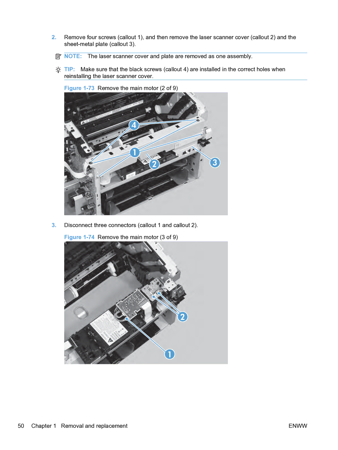
Remove the main motor
Enww
76Remove the main motor 5
Enww
Enww
Reinstall the main motor drive belt
81Main motor drive belt installed correctly
Pickup solenoid
Remove the pickup solenoid
85Remove the pickup solenoid 3 Removal and replacement
Enww
Enww
Engine controller PCA
Remove the engine controller PCA
91Remove the engine controller PCA 3 Removal and replacement
93Remove the engine controller PCA 5
Enww
97Remove the engine controller PCA 9
Reinstall the engine controller PCA
101Reinstall the engine controller PCA 4
Enww
Duplex reverse solenoid
Remove the duplex reverse solenoid
Enww
Enww
Main fan
Remove the main fan
110Remove the main fan 3
Enww
Reinstall the main fan
113Reinstall the main fan
Duplex connector PCA
Remove the duplex connector PCA
116Remove the duplex connector PCA 3
Enww
Scanner components
Document feeder input tray
Document feeder cover
Enww
Document feeder pick arm assembly
Remove the document feeder pick arm assembly
127Remove the document feeder pick arm assembly 4
Document feeder core assembly
Remove the document feeder core assembly
Remove one FFC using the blue tab callout
Post scan pinch rollers
Remove the post scan pinch rollers
Document feeder base assembly
Remove the document feeder base assembly
Enww
Document feeder floating hinges
Remove the document feeder floating hinges
Control panel
Solve problems
Check the control panel for error messages
Problem-solving checklist
Check that the product power is on
Test print functionality
Test the fax receiving functionality
Test copy functionality
Test the fax sending functionality
Try sending a print job from a computer
Menu map
Determine the problem source
Troubleshooting process
General topic Questions
Power subsystem
Power-on checks
Engine diagnostics
Tools for troubleshooting
Individual component diagnostics
Engine test button Perform an engine test
Drum rotation functional check
Components tests
Half self-test functional check
Plug/jack locations
Diagrams
Description
Location of connectors
3Engine controller PCA connectors
4Formatter and fax board connectors
Locations of major components
5Main assemblies
6Rollers, solenoids, and fan
7PCA locations
Cross-sectional view
General timing
Charts
Timing diagram
9General
General circuit diagram
Circuit diagram
Status
HP ToolboxFX
View HP ToolboxFX
Event log
Fax tasks
Fax
Fax phone book
Enww
Fax receive log
Help
Fax send log
Block Faxes
System Settings
Device information
Print quality
Paper handling
Paper types
Service
Print Settings
System setup
Device polling
PCL 5e
Network Settings
PostScript
Configuration
Print a cleaning
Internal print quality test pages
Control panel menus
Print quality troubleshooting tools
Setup menu
Repetitive defect ruler
Quick Forms menu
Reports menu
Fax Setup
Enww
Feature is turned on
System Setup menu
This menu item appears only when the private-receive
Confirm Fax # Off
Ring Volume Medium
Cancel
Volume Settings Alarm Volume Soft
Key-Press Volume Loud Phoneline Volume Off Time/Date
Service menu
Next field
Network Setup menu
Function-specific menus
Confirmation before moving to the next one. After all three
Copy
Feature
Fax
Enww
Control panel message types
Interpret control panel messages
Control panel messages
Scanner Error
Fuser Error
Turn off then on
Fan Error
ADF door is open
Doc. feeder jam
Comm. Error
Canceled fax
Document feeder door is open
Canceled send
Engine comm. Error
Fax is busy
Redial Pending
Canceling recv
Fax memory full
Fax recv. error
Fax Send error
Jam in location
Open door and clear jam
Jam in cartridge area
Jam in output bin
Jam in tray
Jam in print paper path
Load tray 1 TYPE, Size
Fax Setup menu. In the Advanced Setup
Cleaning Page OK to start Manual duplex
Service menu. In the Fax Service menu
Press OK Hardware error
No dial tone
No fax answer
No fax detected
No paper pickup
Remove shipping lock from cartridge
Resend Upgrade
Print failure
Remove shipping material from duplex
Sensor Error
Settings cleared
Used cartridge is installed
Unexpected size in tray
Product picks up multiple sheets of paper
Paper feeds incorrectly or becomes jammed
Product does not pick up paper
Prevent paper jams
Clear jams
Jam locations
Clear jams from the document feeder
Clear jams from the input trays
Enww
Clear jams from inside the product
Enww
Clear jams from the output areas
Clear jams from the duplexer
Enww
Enww
Improve print quality
Use paper that meets HP specifications
Select a paper type
Type of print cartridge Steps to resolve the problem
Print a cleaning
Check the print cartridge
Print the Supplies Status
Inspect the print cartridge for damage
Repeating defects
HP PCL 6 driver
Use the printer driver that best meets your printing needs
Improve print quality for copies
HP UPD PS driver
Enww
Clean the product
Clean the pickup roller
Clean the document feeder pickup rollers and separation pad
Clean the paper path from HP ToolboxFX
Clean the paper path
Clean the scanner glass strip and platen
Clean the paper path from the control panel
Enww
Product does not print
Product does not print or it prints slowly
Product prints slowly
Product does not print or it prints slowly
Solve network problems
Solve connectivity problems
Solve direct-connect problems
Computer is using the incorrect IP address for the product
Computer or workstation might be set up incorrectly
Computer is unable to communicate with the product
Open the secondary service menu
Service mode functions
Secondary service menu
Secondary service menu structure
Product resets
Solve fax problems
Fax troubleshooting checklist
Enww
Troubleshoot fax codes and trace reports
View and interpret fax error codes
Code number Description
View the fax trace report
Print all fax reports
Fax logs and reports
Print individual fax reports
Set the fax error report
Set the fax activity log to print automatically
Set the fax confirmation report
Set the fax-error-correction mode
Change error correction and fax speed
Change the fax speed
An error message displays on the control panel
Solve problems sending faxes
Comm. Error message appears
No dial tone
Fax is busy message appears
Document feeder paper jam
No fax answer message appears
Fax memory full message appears
Scanner error
Faxes can be received, but not sent
Unable to use speed dials
Unable to use fax functions from the control panel
Unable to use group dials
Enww
Fax has a dedicated phone line
Solve problems receiving faxes
Fax does not respond
An answering machine is connected to the product
Telephone handset is connected to the product
Answer Mode setting is set to the Manual setting
Voice mail is available on the fax line
Product uses a fax over IP or VoIP phone service
Product is connected to a DSL phone service
No fax detected message appears
Comm. Error message appears
Receive to PC feature is enabled
Private Receive feature is on
Fax is received but does not print
Cannot send or receive a fax on a PBX line
Sender receives a busy signal
No dial tone
Handset is connected to the product
Solve general fax problems
Faxes are sending slowly
Fax quality is poor
Fax cuts off or prints on two pages
Product updates
Enww
Parts and diagrams
Whole unit replacement part numbers
Order parts by authorized service providers
Order replacement parts
Related documentation and software
Customer self repair parts
How to use the parts lists and diagrams
Service parts
Assembly locations
Locations of major components
2Rollers, solenoids, and fan
3PCA locations
9Cross-sectional view
Covers
5Print engine covers
10Print engine covers
Internal assemblies
Internal assemblies 1
Internal assemblies
Internal assemblies 2
7Internal assemblies 2
12Internal assemblies 2
Internal assemblies 3
8Internal assemblies 3
13Internal assemblies 3
9Internal assemblies 4 Parts and diagrams
Internal assemblies 4
14Internal assemblies 4
Scanner and document feeder ADF main assemblies
Scanner and document feeder ADF main assemblies
11Document feeder assembly parts Parts and diagrams
Document feeder internal components
Document feeder internal components
Alphabetical parts list
17Alphabetical parts list
Alphabetical parts list
Paper pickup assembly RM1-7575-000CN
Numerical parts list
18Numerical parts list
Q7400-00011 Spring, document feeder ADF extension pre-pick
RM1-7542-000CN Fuser film assembly, 220 volt
Enww
Service and support
Hewlett-Packard limited warranty statement
Page
Data stored on the print cartridge
End User License Agreement
Transfer
Enww
Customer support
Repack the product
Product specifications
Acoustic specifications
Physical specifications
Power consumption
Environmental specifications
Regulatory information
FCC regulations
Environmental product stewardship program
Return and recycling instructions
United States and Puerto Rico
Material restrictions
Paper
Non-U.S. returns
Enww
Declaration of conformity
Supplementary Information
March
Boise, Idaho USA
For regulatory topics only
Certificate of Volatility
Volatility
Vcci statement Japan Power cord instructions
Safety statements
Laser safety
Power cord statement Japan EMC statement Korea
Laser statement for Finland
GS statement Germany
Enww
New Zealand Telecom Statements
Additional statements for telecom fax products
EU Statement for Telecom Operation
Additional FCC statement for telecom products US
Telephone Consumer Protection Act US
Industry Canada CS-03 requirements
Enww
Enww
Symbols/Numerics
Index
Macintosh
Jams
Network
Enww
Enww
Page
CE538-90986* *CE538-90986