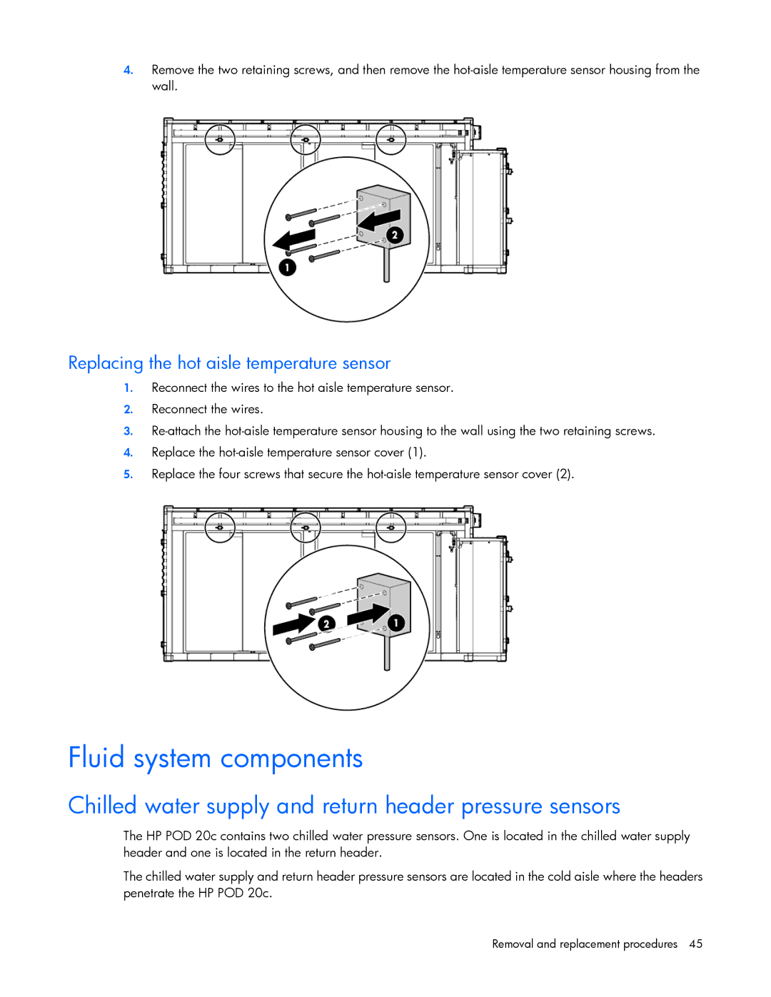
4.Remove the two retaining screws, and then remove the
Replacing the hot aisle temperature sensor
1.Reconnect the wires to the hot aisle temperature sensor.
2.Reconnect the wires.
3.
4.Replace the
5.Replace the four screws that secure the
Fluid system components
Chilled water supply and return header pressure sensors
The HP POD 20c contains two chilled water pressure sensors. One is located in the chilled water supply header and one is located in the return header.
The chilled water supply and return header pressure sensors are located in the cold aisle where the headers penetrate the HP POD 20c.