Server controls, connectors, LEDs, and power
This section describes the controls, connectors, and
Front view
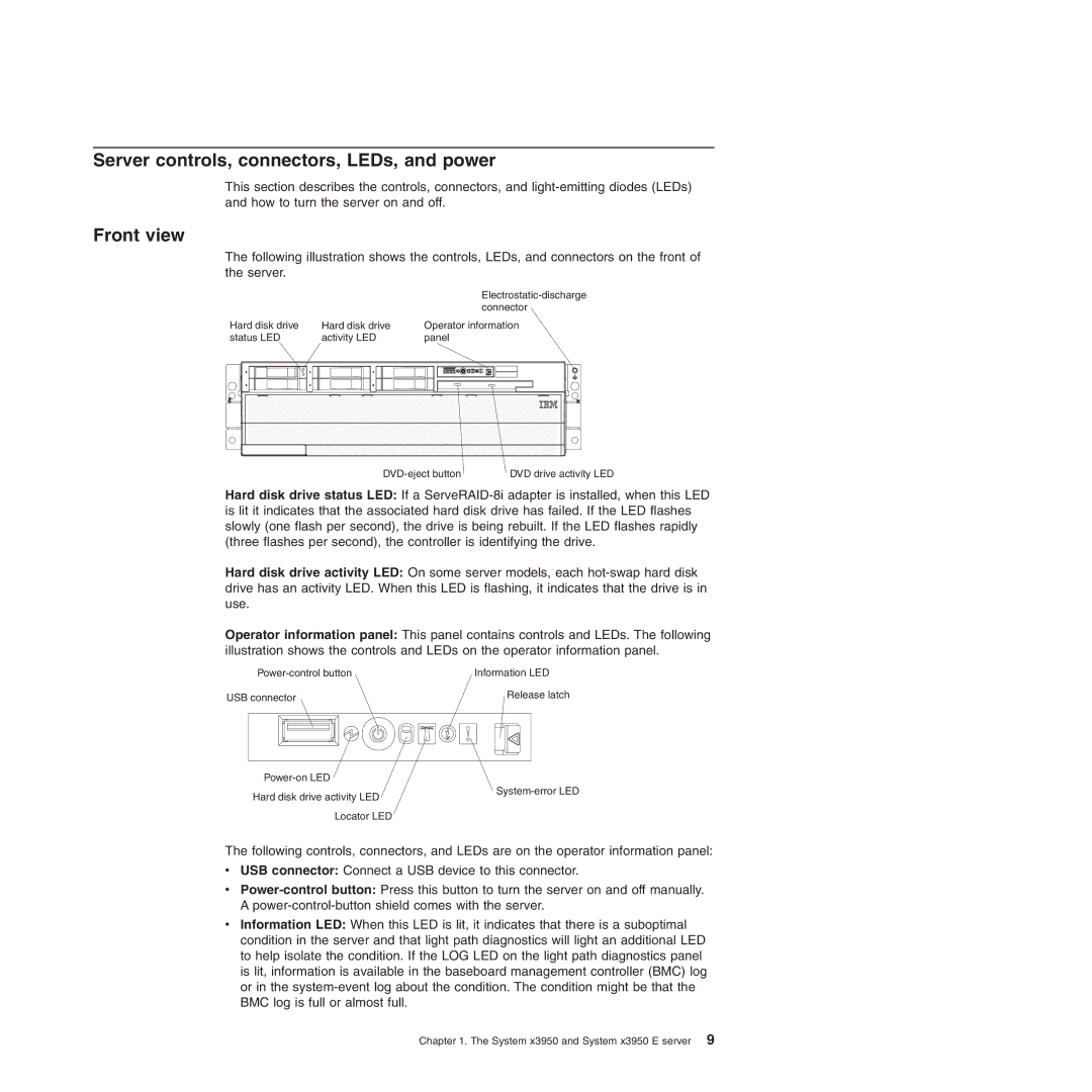
The following illustration shows the controls, LEDs, and connectors on the front of the server.
|
|
|
|
|
|
|
|
|
|
|
|
|
|
|
|
|
|
|
| ||||||||
|
|
|
|
|
|
|
|
|
|
|
|
|
|
|
|
|
|
|
| connector | |||||||
Hard disk drive |
| Hard disk drive | Operator information | ||||||||||||||||||||||||
status LED |
| activity LED | panel | ||||||||||||||||||||||||
|
|
|
|
|
|
|
|
|
|
|
|
|
|
|
|
|
|
|
|
|
|
|
|
|
|
|
|
|
|
|
|
|
|
|
|
|
|
|
|
|
|
|
|
|
|
|
|
|
|
|
|
|
|
|
|
|
|
|
|
|
|
|
|
|
|
|
|
|
|
|
|
|
|
|
|
|
|
|
|
|
|
|
|
DVD drive activity LED |
Hard disk drive status LED: If a
Hard disk drive activity LED: On some server models, each
Operator information panel: This panel contains controls and LEDs. The following illustration shows the controls and LEDs on the operator information panel.
Information LED | |
USB connector | Release latch |
Hard disk drive activity LED Locator LED
The following controls, connectors, and LEDs are on the operator information panel:
vUSB connector: Connect a USB device to this connector.
v
vInformation LED: When this LED is lit, it indicates that there is a suboptimal condition in the server and that light path diagnostics will light an additional LED to help isolate the condition. If the LOG LED on the light path diagnostics panel is lit, information is available in the baseboard management controller (BMC) log or in the
Chapter 1. The System x3950 and System x3950 E server 9