I/O board internal connectors and jumpers
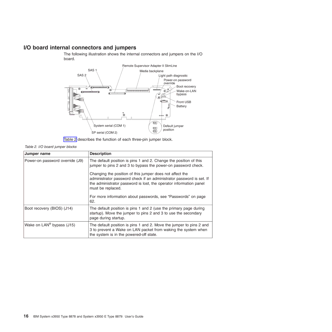
The following illustration shows the internal connectors and jumpers on the I/O board.
| Remote Supervisor Adapter II SlimLine |
SAS 1 | Media backplane |
SAS 2
System serial (COM 1)
SP serial (COM 2)
Light path diagnostic
Boot recovery
Front USB
Battery
1 2 3
| Default jumper |
1 2 3 | position |
|
|
1 2 3 |
|
Table 2 describes the function of each
Table 2. I/O board jumper blocks
Jumper name | Description |
|
|
The default position is pins 1 and 2. Change the position of this | |
| jumper to pins 2 and 3 to bypass the |
| Changing the position of this jumper does not affect the |
| administrator password check if an administrator password is set. If |
| the administrator password is lost, the operator information panel |
| must be replaced. |
| For more information about passwords, see “Passwords” on page |
| 62. |
|
|
Boot recovery (BIOS) (J14) | The default position is pins 1 and 2 (use the primary page during |
| startup). Move the jumper to pins 2 and 3 to use the secondary |
| page during startup. |
|
|
Wake on LAN® bypass (J15) | The default position is pins 1 and 2. Move the jumper to pins 2 and |
| 3 to prevent a Wake on LAN packet from waking the system when |
| the system is in the |
|
|
16IBM System x3950 Type 8878 and System x3950 E Type 8879: User’s Guide