Rear view
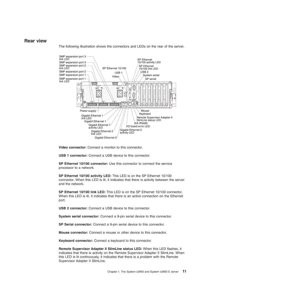
The following illustration shows the connectors and LEDs on the rear of the server.
Video connector: Connect a monitor to this connector.
USB 1 connector: Connect a USB device to this connector.
SP Ethernet 10/100 connector: Use this connector to connect the service processor to a network.
SP Ethernet 10/100 activity LED: This LED is on the SP Ethernet 10/100 connector. When this LED is lit, it indicates that there is activity between the server and the network.
SP Ethernet 10/100 link LED: This LED is on the SP Ethernet 10/100 connector. When this LED is lit, it indicates that there is an active connection on the Ethernet port.
USB 2 connector: Connect a USB device to this connector.
System serial connector: Connect a
SP Serial connector: Connect a
Mouse connector: Connect a mouse or other device to this connector.
Keyboard connector: Connect a keyboard to this connector.
Remote Supervisor Adapter II SlimLine status LED: When this LED flashes, it indicates that there is activity on the Remote Supervisor Adapter II SlimLine. When this LED is lit continuously, it indicates that there is a problem with the Remote Supervisor Adapter II SlimLine.
Chapter 1. The System x3950 and System x3950 E server 11