Protective cover
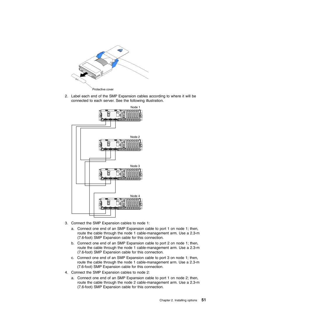
2.Label each end of the SMP Expansion cables according to where it will be connected to each server. See the following illustration.
Node 1
Node 2 |
Node 3 |
Node 4 |
3.Connect the SMP Expansion cables to node 1:
a.Connect one end of an SMP Expansion cable to port 1 on node 1; then, route the cable through the node 1
b.Connect one end of an SMP Expansion cable to port 2 on node 1; then, route the cable through the node 1
c.Connect one end of an SMP Expansion cable to port 3 on node 1; then, route the cable through the node 1
4.Connect the SMP Expansion cables to node 2:
a.Connect one end of an SMP Expansion cable to port 1 on node 2; then, route the cable through the node 2