Protective cover
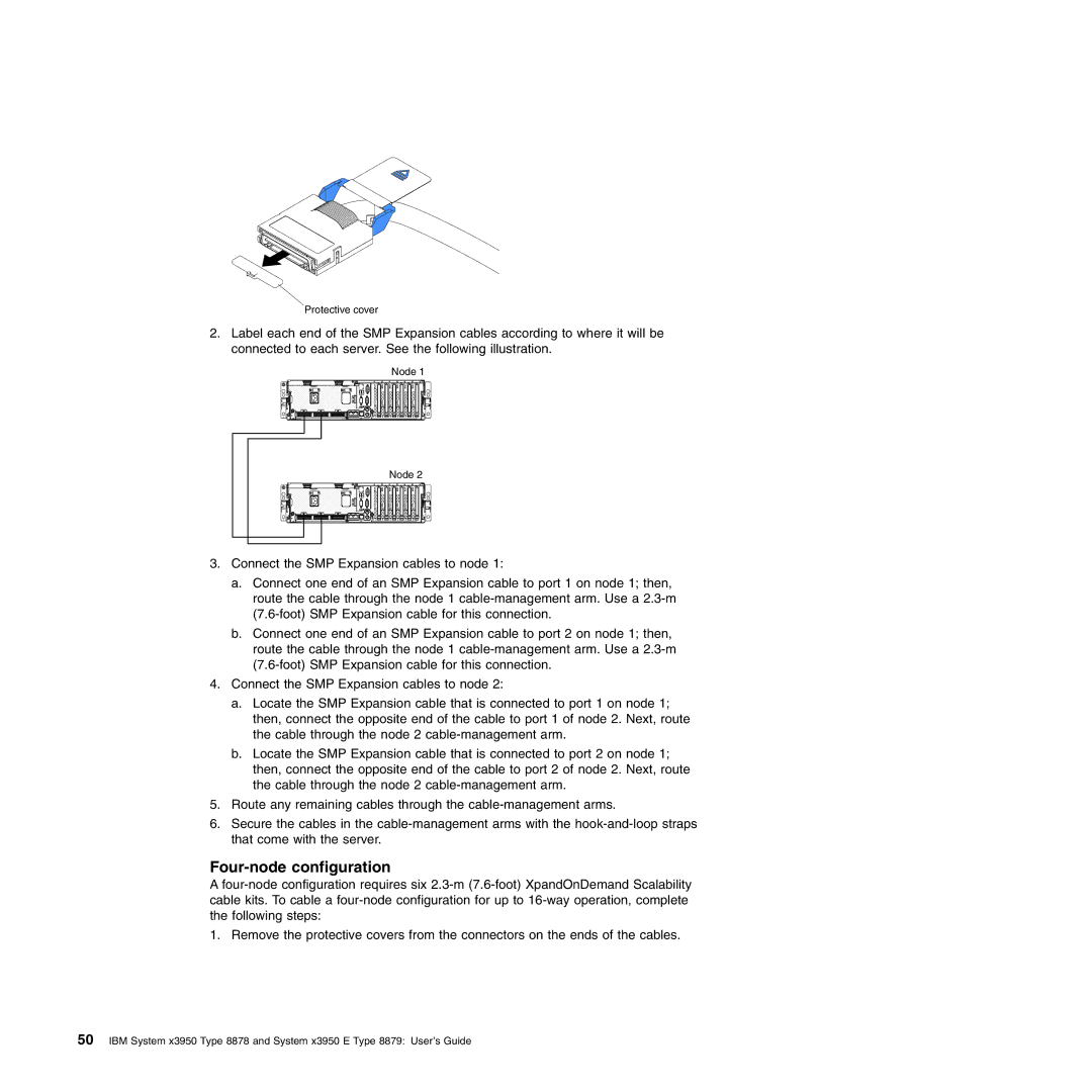
2.Label each end of the SMP Expansion cables according to where it will be connected to each server. See the following illustration.
Node 1
Node 2
3.Connect the SMP Expansion cables to node 1:
a.Connect one end of an SMP Expansion cable to port 1 on node 1; then, route the cable through the node 1
b.Connect one end of an SMP Expansion cable to port 2 on node 1; then, route the cable through the node 1
4.Connect the SMP Expansion cables to node 2:
a.Locate the SMP Expansion cable that is connected to port 1 on node 1; then, connect the opposite end of the cable to port 1 of node 2. Next, route the cable through the node 2
b.Locate the SMP Expansion cable that is connected to port 2 on node 1; then, connect the opposite end of the cable to port 2 of node 2. Next, route the cable through the node 2
5.Route any remaining cables through the
6.Secure the cables in the
Four-node configuration
A
1. Remove the protective covers from the connectors on the ends of the cables.
50IBM System x3950 Type 8878 and System x3950 E Type 8879: User’s Guide