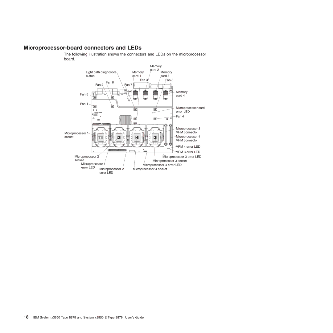
Microprocessor-board connectors and LEDs
The following illustration shows the connectors and LEDs on the microprocessor board.
|
| Memory |
Light path diagnostics | Memory | card 2 |
Memory | ||
button | card 1 | card 3 |
Fan 6 | Fan 3 | Fan 8 |
Fan 7 |
| |
Fan 2 |
| |
Fan 5 |
| Memory |
| card 4 | |
|
|
Fan 1
Microprocessor card error LED
Fan 4
|
|
|
|
| Microprocessor 3 |
Microprocessor 1 |
|
|
|
| VRM connector |
|
|
|
| Microprocessor 4 | |
socket | 1 | 2 | 4 | 3 | |
|
|
|
|
| VRM connector |
|
|
|
|
| VRM 4 error LED |
|
|
|
|
| VRM 3 error LED |
Microprocessor 2 |
| Microprocessor 3 error LED | |
socket |
| Microprocessor 3 socket | |
Microprocessor 1 | Microprocessor 4 error LED | ||
error LED |
| ||
Microprocessor 2 | Microprocessor 4 socket | ||
| |||
error LED
18IBM System x3950 Type 8878 and System x3950 E Type 8879: User’s Guide
