Memory-card connectors
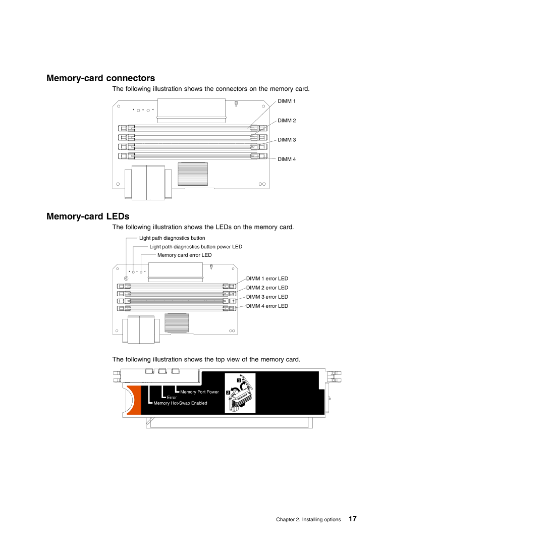
The following illustration shows the connectors on the memory card.
DIMM 1
DIMM 2
DIMM 3
![]() DIMM 4
DIMM 4
Memory-card LEDs
The following illustration shows the LEDs on the memory card.
Light path diagnostics button
Light path diagnostics button power LED
Memory card error LED
DIMM 1 error LED
DIMM 2 error LED
DIMM 3 error LED
DIMM 4 error LED
The following illustration shows the top view of the memory card.
![]() Memory Port Power
Memory Port Power
Error
Memory
Chapter 2. Installing options 17
